High-power high-voltage direct-current contactor

A high-voltage DC, contactor technology, applied in relays, electromagnetic relays, electromagnetic relay details and other directions, can solve the problems of insufficient arc extinguishing effect, low magnetic field strength, unreasonable distribution of magnetic steel, etc., to reduce heat and burn effects , reduce safety hazards and improve the effect of arc extinguishing efficiency

Inactive Publication Date: 2020-07-17
炬恩电气(上海)有限公司
View PDF10 Cites 0 Cited by
  • Summary
  • Abstract
  • Description
  • Claims
  • Application Information

AI Technical Summary

Problems solved by technology

[0003] The current DC contactor mainly has the following defects: 1. The moving contact is usually strip-shaped and its height is low. The arc generated during work is difficult to be elongated by the magnetic force generated by the magnetic steel, and the arc extinguishing effect is insufficient; 2. The magnetic steel distribution of some DC contactors is unreasonable, resulting in too low effective magnetic field strength, which cannot break the arc; 3. The arc extinguishing cavity of the existing DC contactor is unstable, once an explosion occurs in the arc extinguishing cavity , it is easy to break through or fly the arc chute, resulting in local short circuit

Method used


Image

  • High-power high-voltage direct-current contactor
  • High-power high-voltage direct-current contactor
  • High-power high-voltage direct-current contactor

Examples


Embodiment 1

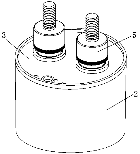
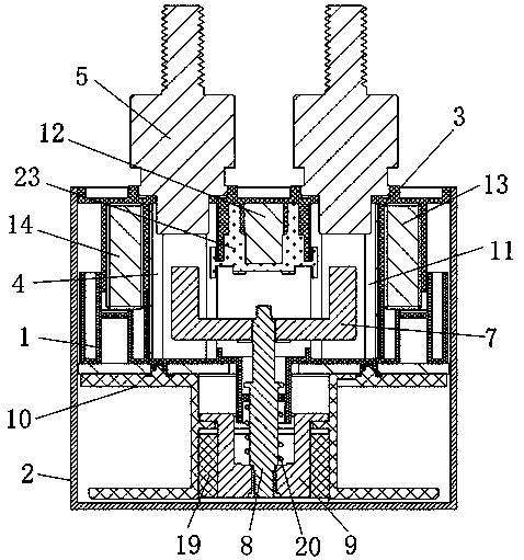
[0026] Embodiment one, such as Figure 1 to Figure 5 As shown, a high-power high-voltage DC contactor includes a base 1, a housing 2 and an arc extinguishing cover 3. The arc extinguishing cover 3 is clamped on the base 1, and the base 1 and the arc extinguishing cover 3 form an arc extinguishing chamber 4. , the arc extinguishing chamber 4 is provided with a fixed contact 5 and a moving contact 6, the fixed contact 5 is fixedly installed on the arc extinguishing cover 3, the cross section of the moving contact 6 is an equilateral trapezoid, the small end of the moving contact 6 is in line with the The positions of the fixed contacts 5 are opposite, the large end of the moving contact 6 is fixedly installed on the moving iron 7, and the moving iron 7 is fixedly connected to the first connecting column 8, and the end of the first connecting column 8 is connected to the moving iron core. 9 is fixedly connected, the moving iron core 9 is rotatably installed in the inner cavity of...

Embodiment 2

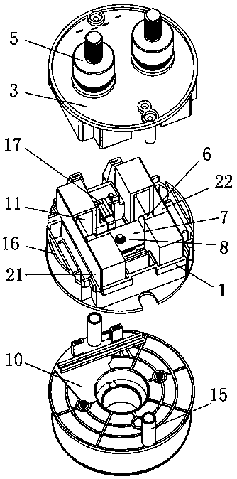
[0030] Embodiment 2, this embodiment is a preferred technical solution of Embodiment 1. A reinforced connecting rod 15 is provided on the take-up frame 10, and the reinforced connecting rod 15 and the arc extinguishing cover 3 are engaged with each other, and the base 1 is fixedly connected with a Buckle 16, and the buckle 16 is engaged with the arc extinguishing cover 3 . The reinforced connecting rod 15 and the arc extinguishing cover 3 are engaged with each other, and the buckle 16 clamps the arc extinguishing cover 3 on the base 1, which can prevent the temperature in the arc extinguishing cover 3 from rising rapidly, and the arc extinguishing cover 3 is blasted or directly rushed away .

Embodiment 3

[0031] Embodiment 3, this embodiment is a preferred technical solution of Embodiment 1, a contact block 17 is fixedly installed on the moving contact iron 7, and a switch 18 corresponding to the contact block 17 is fixedly installed on the top wall of the arc extinguishing cover 3 , the contactor is provided with a synchronous switch 18, when the moving contact iron 7 moves up, the moving contact 6 contacts the static contact 5, and at the same time the contact block 17 moves up together until it contacts the switch contact of the switch 18, the switch 18 is closed, The contactor circuit is connected; when the moving contact 6 is separated from the static contact 5, the contact block 17 is not in contact with the switch 18, and the contactor circuit is disconnected.


PUM


Abstract

The invention discloses a high-power high-voltage direct-current contactor. The high-power high-voltage direct-current contactor comprises a base, a shell and an arc extinguishing cover, the arc extinguishing cover is clamped on the base, and the base and the arc extinguishing cover form an arc extinguishing cavity. A fixed contact and a moving contact are arranged in the arc extinguishing cavity,the fixed contact is fixedly arranged on the arc extinguishing cover, and the cross section of the moving contact is an equilateral trapezoid. The small end of the moving contact is opposite to the fixed contact, and the large end of the moving contact is fixedly arranged on a moving contact iron. The moving contact iron is arranged to be of a three-dimensional structure, and the electric arcs generated by the moving contact and the static contact are lengthened, so that the arc extinguishing efficiency is improved, and the arc extinguishing effect is improved. The magnetic steel is arrangedbetween the moving contacts and at the two sides of the moving contacts, so that an effective magnetic field is increased, and the rapid arc extinguishing can be achieved. Through the reinforcing connecting rod arranged on a take-up frame and the buckle arranged on the base, the explosion-proof protection is carried out on the arc extinguishing cover, and therefore the potential safety hazards arereduced.

Description

technical field [0001] The invention relates to the field of contactors, in particular to a high-power high-voltage DC contactor. Background technique [0002] A DC contactor is a high-power switching device that operates a circuit through a small current and low voltage over a long distance. It is mainly composed of two parts: an electrical contact system and an electromagnetic system, and most of the structures use double break point bridge contacts. and solenoid suction magnetic system. [0003] The current DC contactor mainly has the following defects: 1. The moving contact is usually strip-shaped and its height is low. The arc generated during work is difficult to be elongated by the magnetic force generated by the magnetic steel, and the arc extinguishing effect is insufficient; 2. The magnetic steel distribution of some DC contactors is unreasonable, resulting in too low effective magnetic field strength, which cannot break the arc; 3. The arc extinguishing cavity of...

Claims


Application Information

Patent Timeline
Patent Type & Authority Applications(China)
IPC IPC(8): H01H50/54H01H50/38H01H50/02
CPCH01H50/023H01H50/38H01H50/54
Inventor 不公告发明人
Owner 炬恩电气(上海)有限公司
Why Eureka
Try Eureka