Electric Auxiliary Drive Mechanisms for Bicycles or Motorcycles

An electric auxiliary and driving mechanism technology, which is applied in rider driving, vehicle components, vehicle gearboxes, etc., can solve the problems of design and development difficulty, increased production cost, power unit movement resistance, and inability to completely separate, so as to improve the product Competitiveness, reduced occupied space, reduced development difficulty and the effect of production cost

Active Publication Date: 2021-09-03
JIANGYIN KANGRUI MOLDING TECH CO LTD
View PDF9 Cites 0 Cited by
  • Summary
  • Abstract
  • Description
  • Claims
  • Application Information

AI Technical Summary

Problems solved by technology

[0005] However, when the above-mentioned structure is actually applied, the original structure of the locomotive must be greatly changed, resulting in difficulty in design and development and increased production costs, and because the motor is mechanically connected to the transmission system of the locomotive, the two cannot be fully integrated. Separation, if one of the motor or locomotive engine is damaged, it will cause resistance to the movement of the other power unit, so there will be a serious loss in use

Method used


Image

  • Electric Auxiliary Drive Mechanisms for Bicycles or Motorcycles
  • Electric Auxiliary Drive Mechanisms for Bicycles or Motorcycles
  • Electric Auxiliary Drive Mechanisms for Bicycles or Motorcycles

Examples


Embodiment 1

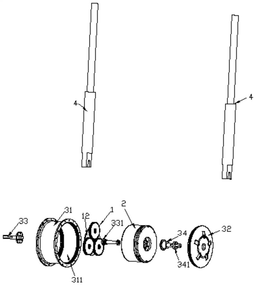
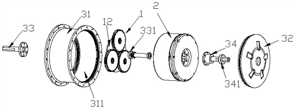
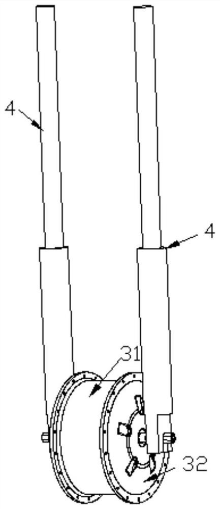
[0032] Such as Figure 1 to Figure 5 shown (for ease of illustration, Figure 5 The drive gear, the first bearing and the two planetary internal gears have been removed), the present invention is an electric auxiliary drive mechanism for a bicycle or a locomotive, including the planetary gear set 1 and the electric power source 2; wherein the planetary gear set 1 There is a ring-shaped planetary external gear 11, which is set at the center of a bicycle or a non-driven wheel (which can be a front wheel) of a motorcycle, and an internal gear seat 12 is arranged at the center of the planetary external gear 11 , at least one planetary internal gear 13 meshing with the planetary external gear 11 is pivotally arranged on the internal gear seat 12 .

[0033] In a feasible embodiment, the non-driving wheel has a hub 31 in the center, and the hub 31 is provided with an accommodating space 311 with an opening on at least one side, and the planetary gear set 1 is arranged in the accommo...

Embodiment 2

[0039] The difference with Embodiment 1 is that technical improvement is carried out on the basis of Embodiment 1, the motor casing is changed, and a transparent observation window is set on the motor casing (the location of the observation window is to avoid the place connected to the wheel spokes on the side of the hub, And the observation window is in the shape of a long strip and the observation window is parallel to the rotation axis of the wheel in the direction) The position of the tempered glass observation window bonded on the annular groove on the side of the motor casing is directly opposite to the driving gear of the planetary gear set (so that in case of failure, Especially after a period of use, the planetary gear set is most likely to occur and the first problem is gear wear. Under normal working conditions, the gears of the planetary gear set have uniform wear on the tooth surface, and the wear along the tooth length direction may have exceeded 30% of the origin...

Embodiment 3

[0041] The difference with Embodiment 2 is that technical improvement is carried out on the basis of Embodiment 2, such as Figure 7 to Figure 9 As shown, among the plurality of observation windows 5 that are fixedly connected (that is, by gluing), at least one observation window is clamped and connected on the motor housing 6, and there is also at least one observation window corresponding to the aforementioned position on the hub 31 to be clamped. connected on the wheel hub (the optimal solution is that three observation windows are movable clamping type, and the positions of these three movable clamping observation windows correspond to the pivot positions of the three planetary internal gears 13, and these three The movable clamping observation windows are arranged in a circular array). And increasing the length of the motor housing is used to set the storage space 8 of the damaged parts (increase the shaft length of the shaft of the drive gear 21 simultaneously); change t...


PUM


Abstract

The invention discloses an electric auxiliary driving mechanism for a bicycle or a motorcycle, which comprises: a planetary gear set arranged at the center of a non-driving wheel (front wheel) of a bicycle or a motorcycle, and an electric power source connected and fixed on a On the support assembly of the non-driving wheel of a bicycle or motorcycle, and the electric power source is meshed with the planetary gear set through a driving gear, so that the power of the electric power source is converted and decelerated through the planetary gear set, and the non-driving wheel can be A large torque auxiliary drive is formed to meet the driving needs of bicycles or motorcycles with heavy loads (heavy loads, climbing steep slopes).

Description

technical field [0001] The invention relates to an electric auxiliary driving mechanism of a bicycle or a locomotive, especially an electric auxiliary mechanism capable of generating a large torque auxiliary driving force without changing the original driving structure of the bicycle or locomotive. Background technique [0002] Bicycles or locomotives have the characteristics of lightness and convenience, and are the main means of transportation that are often used. In order to save fuel consumption and manpower, motorcycles with pure manpower or small displacement engines are the mainstream of means of transportation; however, in practical applications Due to the limitation of manpower or the insufficient output power of small displacement engines, the output power is often insufficient when under heavy load (high load, climbing a steep slope), which may even cause dangerous situations such as insufficient vehicle speed or reverse uphill. Therefore, how to improve the lack ...

Claims


Application Information

Patent Timeline
Patent Type & Authority Patents(China)
IPC IPC(8): B62M6/40B62M11/14B62M11/16
CPCB62M6/40B62M11/14B62M11/16
Inventor 朱卫陈万春庄皓琳
Owner JIANGYIN KANGRUI MOLDING TECH CO LTD
Why Eureka
Try Eureka