Electric auxiliary driving mechanism for bicycle or motorcycle
An electric auxiliary and driving mechanism technology, which is applied in the directions of rider driving, vehicle components, vehicle gearboxes, etc., can solve the problems of difficulty in design and development, increase in production costs, movement resistance of power units, and inability to completely separate, so as to improve products Competitiveness, reduced occupied space, and reduced development difficulty
- Summary
- Abstract
- Description
- Claims
- Application Information
AI Technical Summary
Problems solved by technology
Method used
Image
Examples
Embodiment 1
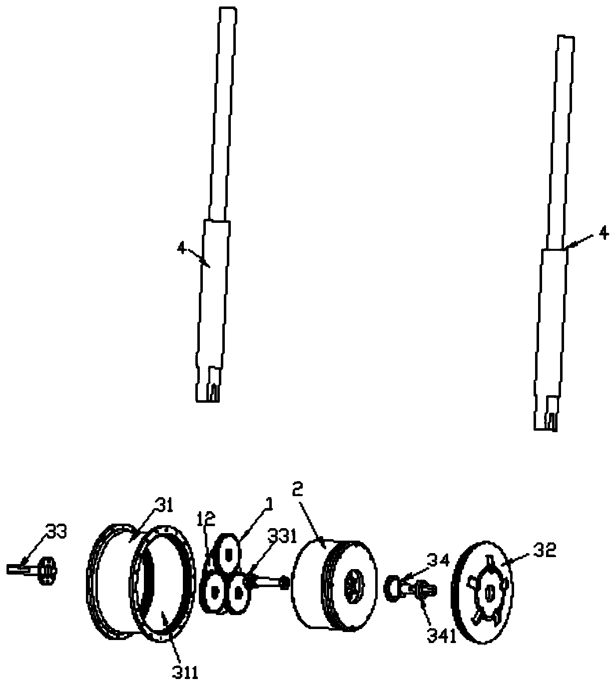
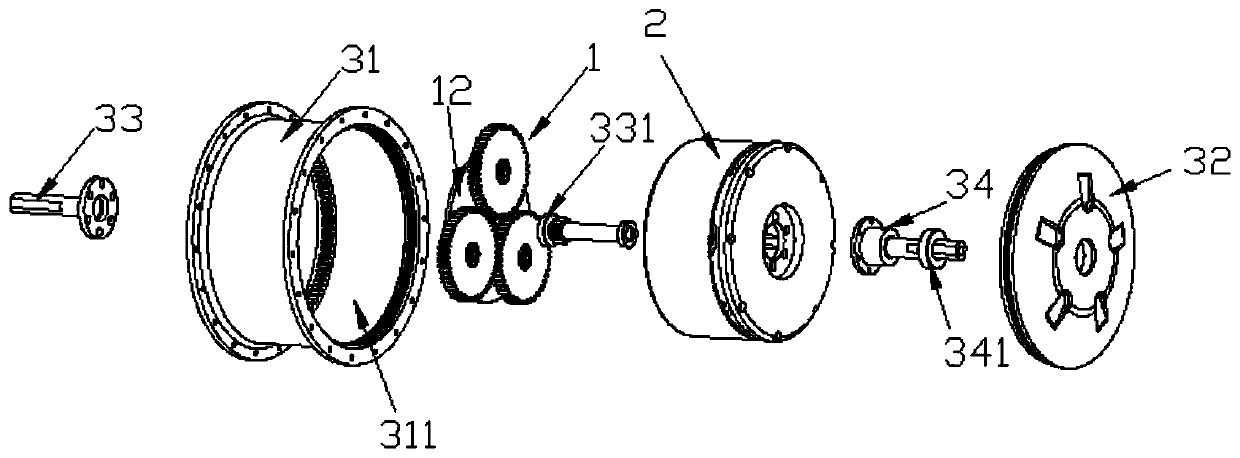
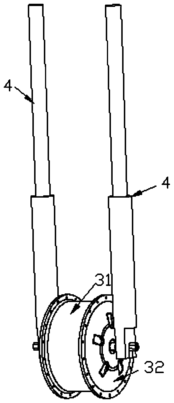
[0032] like Figure 1 to Figure 5 shown (for ease of illustration, Figure 5 The drive gear, the first bearing and the two planetary internal gears have been removed), the present invention is an electric auxiliary drive mechanism for a bicycle or a locomotive, including the planetary gear set 1 and the electric power source 2; wherein the planetary gear set 1 There is a ring-shaped planetary external gear 11, which is set at the center of a bicycle or a non-driven wheel (which can be a front wheel) of a motorcycle, and an internal gear seat 12 is arranged at the center of the planetary external gear 11 , at least one planetary internal gear 13 meshing with the planetary external gear 11 is pivotally arranged on the internal gear seat 12 .
[0033] In a feasible embodiment, the center of the non-driving wheel has a hub 31, the hub 31 is provided with an accommodating space 311 with an opening on at least one side, and the planetary gear set 1 is arranged in the accommodating ...
Embodiment 2
[0039] The difference with Embodiment 1 is that technical improvement is carried out on the basis of Embodiment 1, the motor casing is changed, and a transparent observation window is set on the motor casing (the location of the observation window is to avoid the place connected to the wheel spokes on the side of the hub, And the observation window is in the shape of a long strip and the observation window is parallel to the rotation axis of the wheel in the direction) The position of the tempered glass observation window bonded on the annular groove on the side of the motor casing is directly opposite to the driving gear of the planetary gear set (so that in case of failure, Especially after a period of use, the planetary gear set is most likely to occur and the first problem is gear wear. Under normal working conditions, the gears of the planetary gear set have uniform wear on the tooth surface, and the wear along the tooth length direction may have exceeded 30% of the origin...
Embodiment 3
[0041] The difference with Embodiment 2 is that technical improvement is carried out on the basis of Embodiment 2, such as Figure 7 to Figure 9 As shown, among the plurality of observation windows 5 that are fixedly connected (that is, by gluing), at least one observation window is clamped and connected on the motor housing 6, and there is also at least one observation window corresponding to the aforementioned position on the hub 31 to be clamped. connected on the wheel hub (the optimal solution is that three observation windows are movable clamping type, and the positions of these three movable clamping observation windows correspond to the pivot positions of the three planetary internal gears 13, and these three The movable clamping observation windows are arranged in a circular array). And increasing the length of the motor housing is used to set the storage space 8 of the damaged parts (increase the shaft length of the shaft of the drive gear 21 simultaneously); change t...
PUM
 Abstract
Description
Claims
Application Information
 - R&D
- Intellectual Property
- Life Sciences
- Materials
- Tech Scout
- Unparalleled Data Quality
- Higher Quality Content
- 60% Fewer Hallucinations
Browse by: Latest US Patents, China's latest patents, Technical Efficacy Thesaurus, Application Domain, Technology Topic, Popular Technical Reports.
© 2025 PatSnap. All rights reserved.Legal|Privacy policy|Modern Slavery Act Transparency Statement|Sitemap|About US| Contact US: help@patsnap.com


