Device for continuously adjusting distance between diffuser and spray pipe of hypersonic speed free jet wind tunnel

A hypersonic, diffuser technology, used in measuring devices, testing of machine/structural components, instruments, etc., can solve the problems of inability to achieve continuous adjustment of Δd, inability to store the adjustment section, time-consuming, labor-intensive, and safety. The effect of preparation efficiency, simple structure, and shortened adjustment time

Pending Publication Date: 2020-07-24
中国空气动力研究与发展中心超高速空气动力研究所
View PDF0 Cites 13 Cited by
  • Summary
  • Abstract
  • Description
  • Claims
  • Application Information

AI Technical Summary

Problems solved by technology

[0005] 1) When adjusting the distance △d between the outlet of the nozzle and the inlet of the diffuser, it is necessary to install the spreader at different positions to complete the disassembly and installation of the relevant parts of the diffuser, which is time-consuming and labor-intensive;
[0006] 2) The adjustment position is a discrete point, and the continuous adjustment of △d cannot be realized;
[0007] 3) In order to meet the different requirements of △d, it is necessary to configure a lot of adjustment sections with different lengths, and the cost is high;
[0008] 4) Due to the limitation of the internal space of the test section, the adjustment section for replacement cannot be stored in the test section. Therefore, every time adjustment is made, the staff needs to transport the adjustment section in and out from the test section. The transportation process is time-consuming and laborious and there is a certain degree of safety Hidden danger

Method used


Image

  • Device for continuously adjusting distance between diffuser and spray pipe of hypersonic speed free jet wind tunnel
  • Device for continuously adjusting distance between diffuser and spray pipe of hypersonic speed free jet wind tunnel
  • Device for continuously adjusting distance between diffuser and spray pipe of hypersonic speed free jet wind tunnel

Examples


Embodiment 1

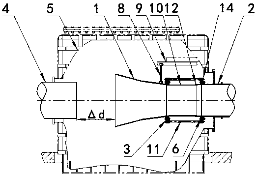
[0051] The device for continuously adjusting the distance between the diffuser and the nozzle of a hypersonic free-jet wind tunnel in this embodiment is installed in a hypersonic wind tunnel, and the distance between the inlet of the diffuser and the outlet of the nozzle is continuously within the range of 1.1m to 1.8m. adjustable.

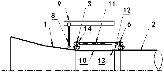
[0052] There are 4 threaded rods 11 and 16 adjusting nuts 14 in the device for continuously adjusting the distance between the hypersonic free jet wind tunnel diffuser and the nozzle in this embodiment.

[0053] The specific working process is as follows:

[0054] a. According to the needs of the wind tunnel test, determine the distance △d between the diffuser inlet and the nozzle outlet, measure the current distance △d1 between the diffuser inlet and the nozzle outlet, calculate the adjusted distance △d2=△d-△d1, determine Adjust the movement distance Δd2 of the nut 14;

[0055] b. Loosen the adjusting nuts 14 on the inside and outside of the fl...


PUM


Abstract

The invention discloses a device for continuously adjusting the distance between a diffuser and a spray pipe of a hypersonic speed free jet wind tunnel. The device comprises horizontal distance adjusting mechanisms and a sliding mechanism, and the horizontal distance adjusting mechanisms are installed on a diffuser equal-straight section and evenly distributed in the circumferential direction of the diffuser equal-straight section; and the sliding mechanism is a vertically-installed adjusting rod, the lower end of the adjusting rod is fixed to a diffuser contraction section, the upper end of the adjusting rod is hung on a horizontal guide rail fixed to the upper wall face of a test section, and the adjusting rod moves front and back along a horizontal guide rail to drive the horizontal distance adjusting mechanisms to move front and back to adjust the distance delta d between the diffuser contraction section and the spray pipe. The device for continuously adjusting the distance betweenthe diffuser and the spray pipe of the hypersonic velocity free jet flow wind tunnel is simple in structure and low in manufacturing cost; the use process is convenient, efficient and safe, the adjustment time can be greatly shortened, and the test preparation efficiency is improved; and the distance between the diffuser and the spray pipe is large in adjustment range, and wind tunnel test requirements can be flexibly met.

Description

technical field [0001] The invention belongs to the technical field of hypersonic wind tunnel equipment, in particular to a device for continuously adjusting the distance between a hypersonic free-jet wind tunnel diffuser and a nozzle. Background technique [0002] The main function of the hypersonic free-jet wind tunnel diffuser is to decelerate and pressurize the hypersonic flow at the outlet of the nozzle to increase the static pressure at the diffuser outlet, and isolate the influence of the downstream back pressure of the diffuser on the wind tunnel flow field. Maintain the normal operation of the wind tunnel. Hypersonic free-jet wind tunnel diffusers are usually designed as a combination of "contraction section-equal straight section-expansion section". [0003] For a hypersonic free-jet wind tunnel, the nozzle is located at the front end of the test section, the diffuser is located at the rear end of the test section, and the distance between the outlet of the nozzle...

Claims


Application Information

Patent Timeline
Patent Type & Authority Applications(China)
IPC IPC(8): G01M9/04
CPCG01M9/04
Inventor 范孝华孙启志凌岗许晓斌杨波巢根明
Owner 中国空气动力研究与发展中心超高速空气动力研究所
Why Eureka
Try Eureka