Calcining system for nickel-iron alloy production

A nickel-iron alloy and calcination technology, which is applied in metal processing equipment, forming tools, manufacturing tools, etc., can solve the problems of stamping only one product, difficulty in taking out, etc., and achieve the effects of improving stability, moving smoothly, and improving cutting efficiency

Inactive Publication Date: 2020-02-21
辰溪县宏林新材料有限公司
View PDF0 Cites 1 Cited by
  • Summary
  • Abstract
  • Description
  • Claims
  • Application Information

AI Technical Summary

Problems solved by technology

[0004] The purpose of the present invention is to propose a calcination system for nickel-iron alloy production in order to solve the p

Method used


Image

  • Calcining system for nickel-iron alloy production
  • Calcining system for nickel-iron alloy production
  • Calcining system for nickel-iron alloy production

Examples


Embodiment 1

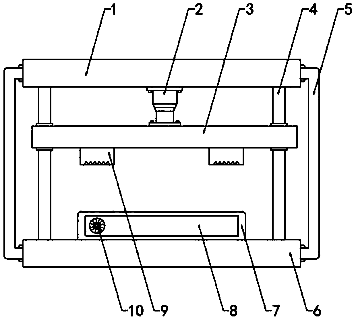
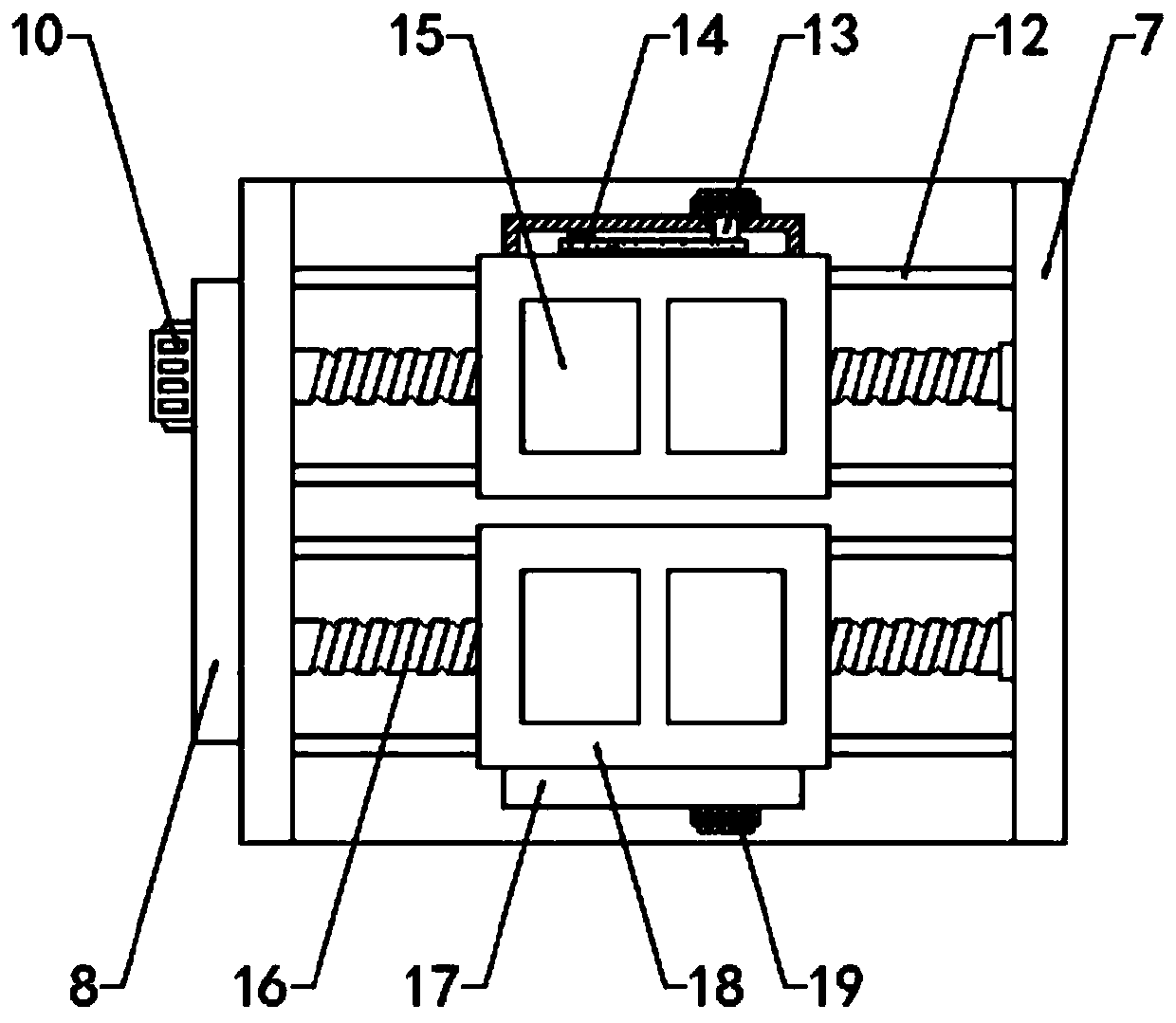
[0035] see Figure 1-5 , a calcination system for nickel-iron alloy production, comprising a top plate 1, a bottom plate 6 and a support 5, the support 5 is fixed between the top plate 1 and the bottom plate 6, the bottom of the top plate 1 is provided with a moving plate 3 and the lower surface wall of the moving plate 3 is fixed There are two dies 9, a cylinder 2 is arranged between the moving plate 3 and the top plate 1, one end of the cylinder 2 is fixed on the lower surface wall of the top plate 1, the other end is fixed on the upper surface wall of the moving plate 3, and the upper surface wall of the bottom plate 6 Fixed frame 7 is fixed, and the inside of fixed frame 7 is provided with two longitudinally distributed threaded rods 16, and the inner wall of threaded rod 16 and fixed frame 7 is for rotation fit, and the exterior of two threaded rods 16 is screwed with lower mold base 18, The side wall of fixed frame 7 is fixed with the first driving mechanism that drives ...

Embodiment 2

[0038] see figure 1 , there are two guide rods 4 symmetrically running through the moving plate 3, the vertical ends of the guide rods 4 are respectively fixed with the top plate 1 and the bottom plate 6, the moving plate 3 and the guide rods 4 are slidingly fitted, which can prevent the moving plate 3 from moving vertically. The offset occurs during the movement in the direction, which improves the stability of the device.

[0039] The difference from Example 1 is that

Embodiment 3

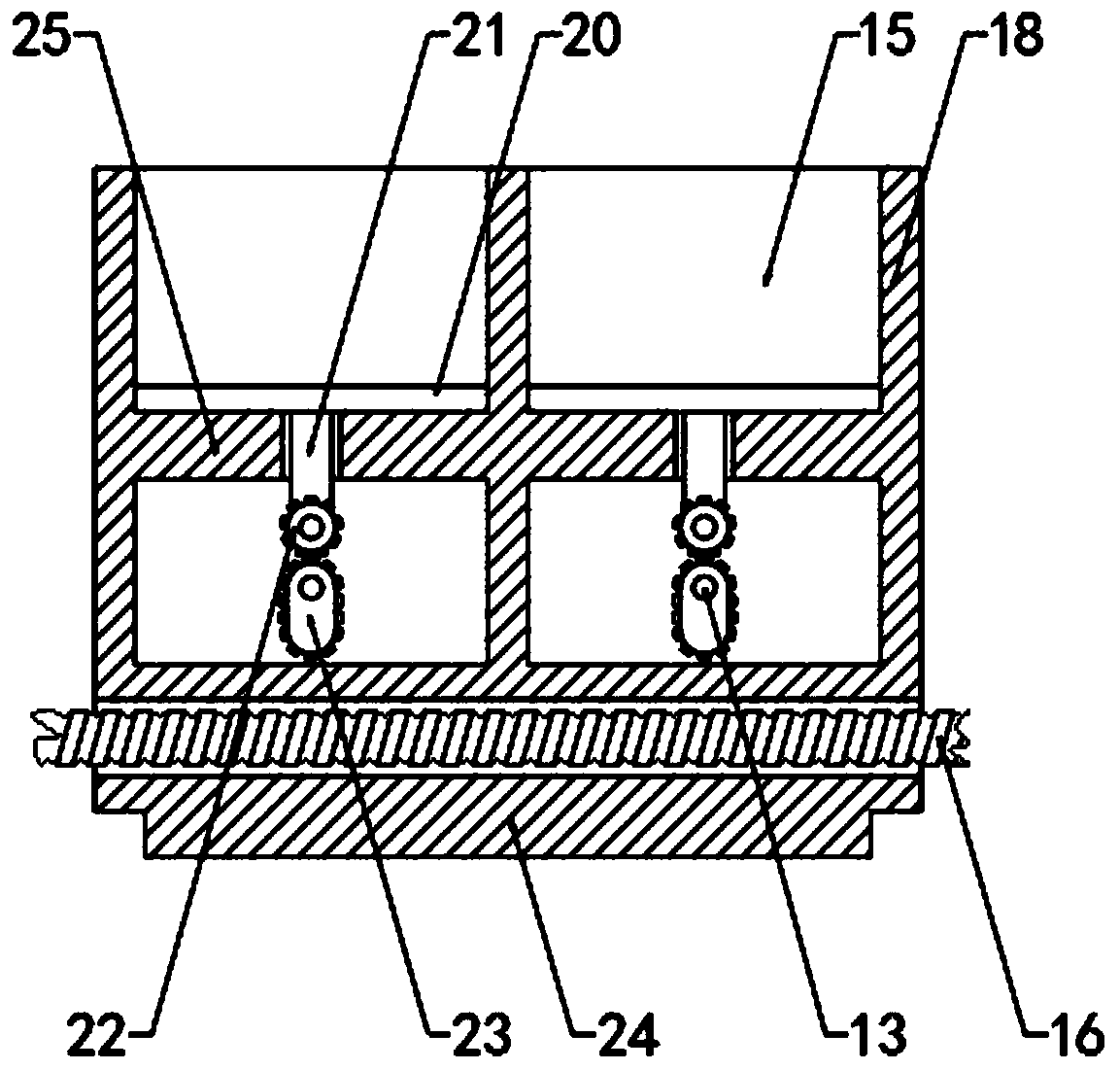
[0041] see image 3 and Figure 5 , the second drive mechanism includes a transmission shaft 13 arranged at the bottom of the placing table 25, the second gear 23 is sleeved on the outside of the transmission shaft 13, the vertical ends of the second gear 23 are semicircular, the middle is rectangular, and the second The gear 23 and the transmission shaft 13 are eccentrically arranged. The lower surface wall of the push plate 20 is fixed with a push rod 21. The push rod 21 runs through the placement table 25 and is provided with a first gear 22. The first gear 22 and the push rod 21 are in rotation. The first gear 22 is engaged with the second gear 23, and the side wall of the lower mold base 18 is fixed with a second fixed cover 17, and the transmission shaft 13 penetrates into the inner cavity of the second fixed cover 17 and is connected by the second belt 14. The second motor 19 for driving the transmission shaft 13 is fixed on the side wall of the second fixed cover 17 ,...


PUM


Abstract

The invention discloses a calcining system for nickel-iron alloy production. The calcining system comprises a top plate, a bottom plate and a support, wherein a movable plate is arranged at the bottomof the top plate, and two punching dies are fixed to the lower surface wall of the movable plate; an air cylinder is arranged between the movable plate and the top plate; a fixing frame is fixed to the upper surface wall of the bottom plate; two longitudinally-distributed threaded rods are arranged in the fixing frame; and a lower die base is screwed to the outer parts of the two threaded rods. In the calcining system, the two lower die bases are arranged on the upper surface wall of the fixing frame, a plurality of female dies are formed in the upper surface walls of the lower die bases in the longitudinal direction, the two punching dies are fixed to the lower surface wall of the movable plate, and two products can be punched at a time; and through the arrangement of a first motor, a first belt and the threaded rods, the lower die bases can move in the front-back direction, punching of the multiple products is achieved, and compared with a traditional punching device, the efficiencyis higher.

Description

technical field [0001] The invention relates to the technical field of nickel-iron alloy production and processing, in particular to a calcination system for nickel-iron alloy production. Background technique [0002] Nickel-iron alloys are all alloys. The main components of ferronickel are nickel and iron, and it also contains Cr, Si, S, P, C and other impurity elements. Chromium-nickel stainless steel is the main stainless steel variety that consumes nickel. Due to its excellent comprehensive performance, it is widely used, accounting for 60% to 75% of the total output. The increase in stainless steel production will drive the growth of nickel metal consumption. With the gradual subsidence of the financial crisis, the price of nickel has returned to more than 20,000 US dollars. important position. [0003] In the process of production and calcination of nickel-iron alloy, stamping molds are required to stamp it. Traditional stamping molding can only stamp one piece at a...

Claims


Application Information

Patent Timeline
IPC IPC(8): B21D37/14B21D37/12B21D22/02
CPCB21D22/022B21D37/12B21D37/14
Inventor 邓讳
Owner 辰溪县宏林新材料有限公司
Why Eureka
Try Eureka