Metal sheet drilling equipment for production and machining

A technology for drilling equipment and metal sheets, which is used in metal processing equipment, perforating tools, manufacturing tools, etc., can solve the problems of cumbersome operations, inability to collect fragments of metal sheets, and inability to transport and feed metal sheets.

Pending Publication Date: 2021-05-18
谭润华
View PDF3 Cites 0 Cited by
  • Summary
  • Abstract
  • Description
  • Claims
  • Application Information

AI Technical Summary

Problems solved by technology

[0005] In order to overcome the disadvantages that the metal sheet cannot be evenly conveyed and loaded, and the operation is cumbersome, and the fragments of the metal sheet cannot be collected in time when the metal sheet is drilled in the appeal patent, the technical problem to be solved by the present invention is to provide A kind of metal sheet drilling equipment for production and processing with relatively simple operation, which can evenly convey and load metal sheets, and can timely collect the remaining metal sheet fragments after drilling

Method used


Image

  • Metal sheet drilling equipment for production and machining
  • Metal sheet drilling equipment for production and machining
  • Metal sheet drilling equipment for production and machining

Examples


Embodiment 1

[0024] A metal sheet drilling equipment for production and processing, such as figure 1 , figure 2 with Figure 4 As shown, it includes a bottom plate 1, a first fixed block 2, a second fixed block 3, a blanking frame 6, a stamping mechanism 4 and a material collection mechanism 7, and the left side of the top of the bottom plate 1 is connected with the first fixed block 2, and the bottom plate 1 The left rear side of the top is connected with the second fixed block 3, the right side of the bottom plate 1 top is connected with the blanking frame 6, the stamping mechanism 4 is connected between the bottom plate 1 and the top of the second fixed block 3, the left front side of the bottom plate 1 top Be connected with collection mechanism 7.

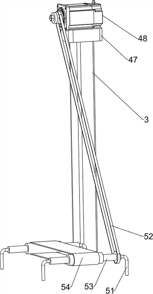
[0025] The stamping mechanism 4 includes a first fixed elbow 41, a telescopic rod 42, a telescopic spring 43, a first fixed plate 44, a stamping block 45, a slide rail 46, a second fixed plate 47, a driving motor 48, and a second fixed e...

Embodiment 2

[0029] On the basis of Example 1, such as image 3 with Figure 5 As shown, a transmission mechanism 5 is also included, and the transmission mechanism 5 includes a third fixed elbow 51, a belt drive group 52, a transmission rod 53 and a conveyor belt 54, and the right side of the bottom plate 1 top is connected with two third fixed elbows 51 , the tops of the two third fixed elbows 51 are rotatably connected with a transmission rod 53, and a conveyor belt 54 is wound between the two transmission rods 53, between the rear part of the right transmission rod 53 and the output shaft of the drive motor 48 A belt drive group 52 is connected between them.

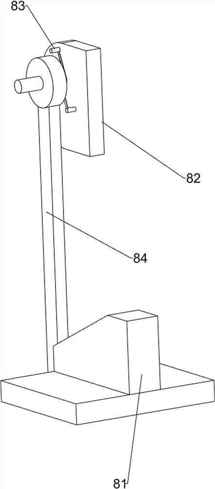
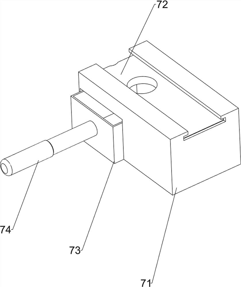
[0030] Also includes a toggle mechanism 8, the toggle mechanism 8 includes a wedge block 81, a fourth fixed plate 82, a torsion spring 83, a toggle block 84 and a roller 85, and a wedge block is connected between the bottom plate 1 and the left side of the pedestal 71 81, the lower part of the left side of the stamping block 45...


PUM


Abstract

The invention relates to metal sheet drilling equipment, in particular to metal sheet drilling equipment for production and machining. According to the technical problem, the metal sheet drilling equipment for production and machining is simple to operate, can uniformly convey and feed metal sheets, and can timely collect residual metal sheet fragments after drilling. In order to solve the technical problem, the metal sheet drilling equipment for production and machining comprises a first fixing block connected to one side of a bottom plate, a second fixing block connected to the other side of the bottom plate, a discharging frame connected to the side, close to the second fixing block, of the bottom plate, a stamping mechanism connected between the bottom plate and the second fixing block, and a material collecting mechanism connected to the side, close to the first fixing block, of the bottom plate. The metal sheet drilling equipment has the following advantages that through the cooperation between a stamping mechanism and the material collecting mechanism, the metal sheets can be stamped.

Description

technical field [0001] The invention relates to a sheet metal drilling device, in particular to a sheet metal drilling device for production and processing. Background technique [0002] In the process of parts production and manufacturing, when people need to drill the metal sheet, it is generally done by manually holding the electric drill while pressing the metal sheet and drilling it multiple times on the other side. The drilling efficiency of the sheet is low, and the labor intensity of the manual operation is relatively high. [0003] After searching, the patent publication number is: the patent of CN208178209U, which discloses a double-joint metal sheet punching die, which includes: top plate, bottom plate, base, punch base, punching needle, pressure column, baffle, gasket groove , lifting rod, spring base and spring ring, the top plate is a rectangular plate, the punch base is installed at the bottom of the top plate, a pressure column and two perforating pins are i...

Claims


Application Information

Patent Timeline
IPC IPC(8): B21D28/34B21D43/12
CPCB21D28/34B21D43/12
Inventor 谭润华
Owner 谭润华
Why Eureka
Try Eureka