A punch with positioning function

A punching machine and functional technology, applied in the field of punching machines with positioning function, can solve the problems of not being able to satisfy customers, inconvenient positioning of stamping blocks, etc., and achieve the effects of preventing damage, simple structure, and convenient operation

Active Publication Date: 2021-06-08
台州市钟氏电机有限公司
View PDF6 Cites 0 Cited by
  • Summary
  • Abstract
  • Description
  • Claims
  • Application Information

AI Technical Summary

Problems solved by technology

Moreover, the punching machine can automatically feed materials, and the punching machine can also clean up the waste generated during punching, but this kind of punching machine is not convenient for positioning the punching block, and cannot meet the needs of customers

Method used


Image

  • A punch with positioning function
  • A punch with positioning function
  • A punch with positioning function

Examples


Embodiment Construction

[0025] The following will clearly and completely describe the technical solutions in the embodiments of the present invention with reference to the accompanying drawings in the embodiments of the present invention. Obviously, the described embodiments are only some, not all, embodiments of the present invention.

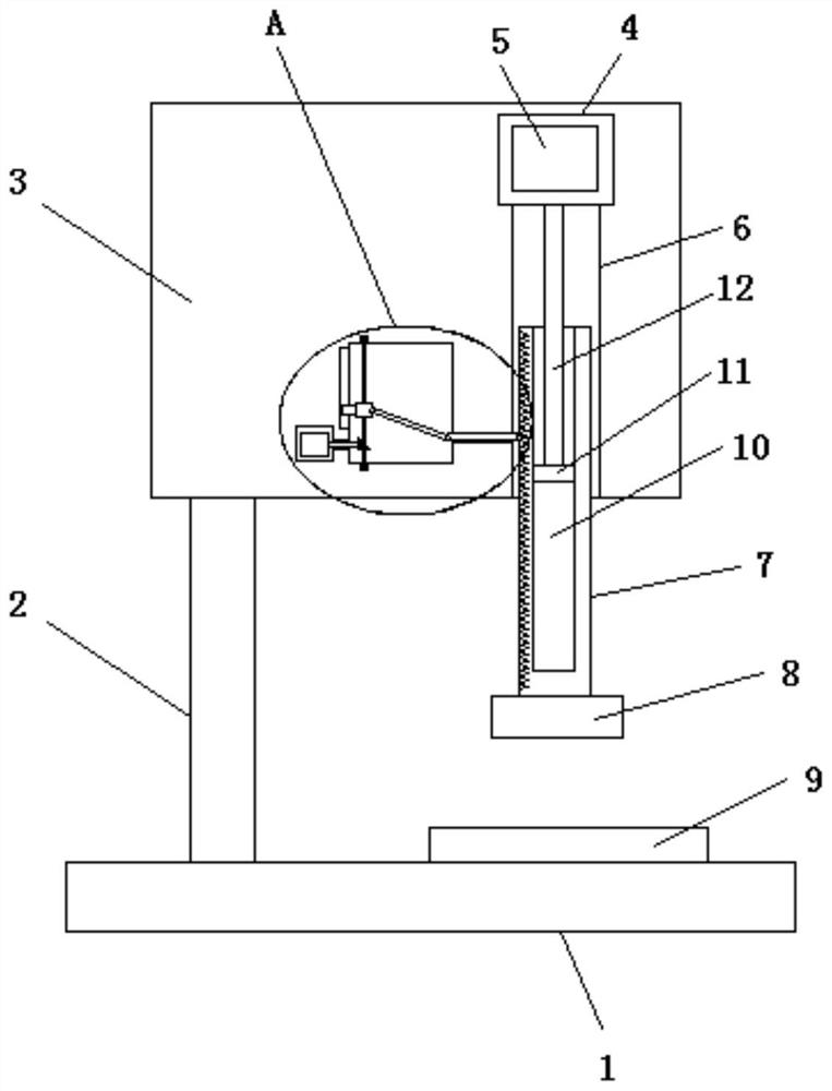
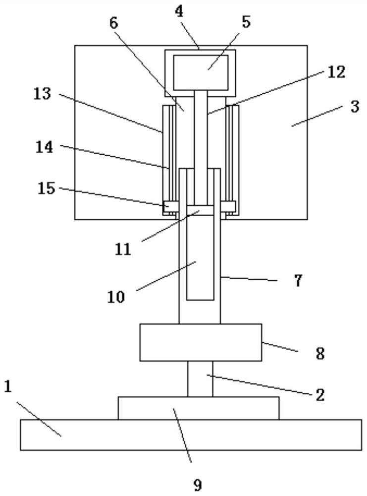
[0026] refer to Figure 1-5 , a punch press with a positioning function, comprising a base 1, a pillar 2 is fixedly installed on the top side of the base 1, an upper module 3 is fixedly installed on the top side of the pillar 2, and a first motor cavity 4 is opened on the upper module 3, and the first A first motor 5 is fixedly installed in the motor chamber 4, and a through hole 6 is opened on the inner wall of the bottom side of the first motor chamber 4, and a sliding rod 7 is slidably installed in the through hole 6, and the bottom end of the sliding rod 7 extends to the through hole 6 A stamping block 8 is fixedly installed on the outside, a thread groove 10 is ...


PUM


Abstract

The invention discloses a punching machine with a positioning function, which comprises a base, a pillar is fixedly installed on the top side of the base, an upper module is fixedly installed on the top side of the pillar, a first motor chamber is opened on the upper module, and a first motor chamber The first motor is fixedly installed inside, and a through hole is opened on the inner wall of the bottom side of the first motor cavity, and a slide bar is slidably installed in the through hole, and the bottom end of the slide bar extends out of the through hole and is fixedly installed with a stamping block, the slide bar There is a threaded groove on the top of the threaded groove, and a threaded block is installed in the threaded groove. The top side of the threaded block is fixedly installed with a main shaft. The top of the main shaft extends into the cavity of the first motor and is fixedly connected with the output shaft of the first motor. There is a second motor cavity, a second motor is fixedly installed in the second motor cavity, and a cavity is opened on the upper module. The invention positions the stamping block after stamping to prevent the reaction force from damaging the thread block and the thread groove, and has simple structure and convenient operation.

Description

technical field [0001] The invention relates to the technical field of positioning, in particular to a punch press with a positioning function. Background technique [0002] A punch press is a stamping press. In national production, the stamping process has the advantages of saving materials and energy, high efficiency, low technical requirements for operators, and the ability to produce products that cannot be achieved by mechanical processing through various mold applications. Its use is more and more extensive. [0003] Patent No. 201611141532.2, an invention patent for a high-precision punch press, discloses a punch press, including a base, a support shaft, a sleeve, a first housing, a second housing, a connecting plate, a turntable, a first gear, Rotary mechanism, driving mechanism, impact mechanism, positioning mechanism and feeding mechanism, the driving mechanism includes a first motor, a first pulley, a second pulley, a belt, a transmission shaft, a second gear, a...

Claims


Application Information

Patent Timeline
Patent Type & Authority Patents(China)
IPC IPC(8): B21D22/02B21D37/14
CPCB21D22/02B21D37/14
Inventor 罗厚镇
Owner 台州市钟氏电机有限公司
Why Eureka
Try Eureka