
Stepped imaging method for mobile CT system

An imaging method and pre-moving technology, applied in the field of medical imaging, can solve problems such as geometric distortion, artifact geometry, and distortion, and achieve the effects of reducing artifacts, reducing geometric distortion, and great flexibility

Active Publication Date: 2020-07-28
NANJING ANKE MEDICAL TECH CO LTD
View PDF8 Cites 3 Cited by
  • Summary
  • Abstract
  • Description
  • Claims
  • Application Information

AI Technical Summary

Problems solved by technology

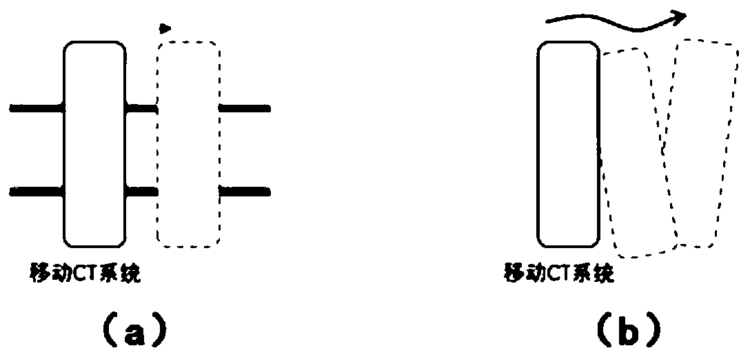
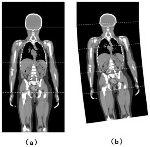
If there is no precise movement of the guide rail in the mobile CT system, the traditional CT algorithm will bring serious artifacts and geometric distortion, such as image 3 shown
These movements can cause severe artifacts and geometric distortion if not corrected for

Method used


Image

  • Stepped imaging method for mobile CT system
  • Stepped imaging method for mobile CT system
  • Stepped imaging method for mobile CT system

Examples


Embodiment Construction

[0034] The present invention will be further described below in conjunction with the accompanying drawings.

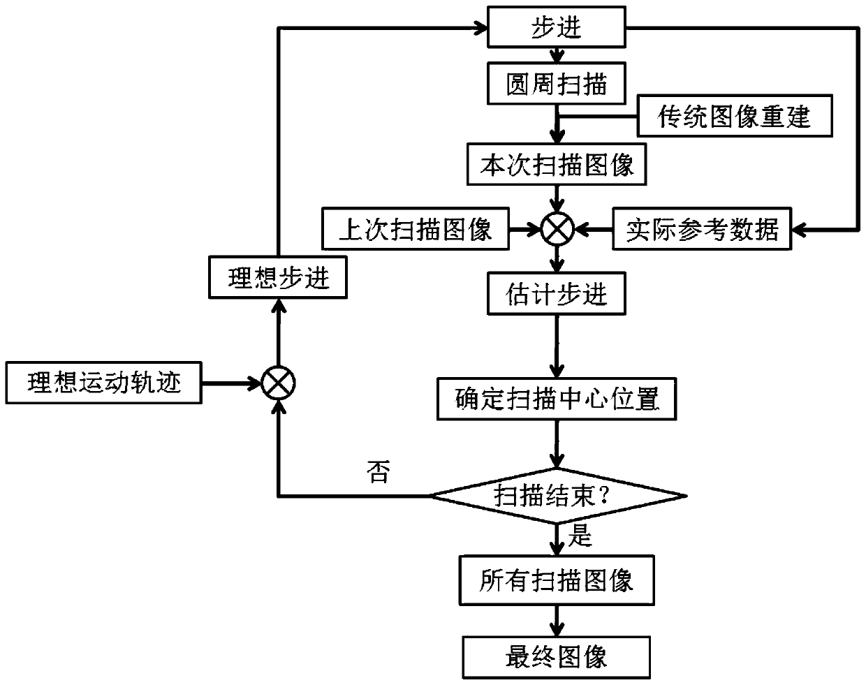
[0035] The invention discloses a step-by-step imaging method of a mobile CT system, which is applied to the mobile CT system, does not rely on guide rails for scanning, but relies on the movement of driving wheels to control the CT machine, and conducts imaging on patients at different positions Step scan and obtain CT images that meet clinical requirements.

[0036] The method proposed by the present invention divides the whole area to be scanned into several step scanning areas, uses circular scanning to scan in each step scanning area, and after all the step scanning is completed, according to the inertial navigation unit (hereinafter referred to as IMU) and the scanned image information, and integrate all the data to obtain an overall reconstructed image. The movement of each step scan here is usually realized by driving wheels. For example, for the CT machine to...


PUM


Abstract

The invention discloses a stepped imaging method for a mobile CT system. The method comprises the following steps of dividing a whole to-be-scanned region into a plurality of stepped scanning regions,enabling a CT machine to start scanning from the first stepped scanning region to obtain scanning data, and carrying out reconstruction to obtain a scanning image; calculating ideal stepping, movingto the next stepped scanning region in a stepping manner, and carrying out scanning reconstruction to obtain a scanning image; according to reference stepping calculated by an inertial navigation unitand the scanning images of the two stepped scanning regions before and after movement, calculating estimated stepping and an actual scanning center position after movement; judging whether the scanning regions already cover the whole to-be-scanned region or not; and if scanning is completed, fusing the scanning images of the stepped scanning regions and the estimated stepping obtained by calculation into final reconstruction body data. According to the method provided by the invention, a motion trail of a scanning center of the CT machine can be accurately estimated under the condition of noguide rails, so that the more accurate scanning images are obtained, and artifacts and geometric distortion are reduced.

Description

technical field [0001] The invention belongs to the field of medical imaging, in particular to a step-by-step imaging method of a mobile CT system. Background technique [0002] CT system is a large medical system that can scan patients in 3D and obtain 3D image information. However, the traditional CT system has relatively strict requirements on the site, and must have a special shielding room and corresponding site requirements. The entire system is fixed on the ground, so there are relatively large restrictions on usage scenarios. Especially for operating room, intensive care unit (ICU) and other occasions, the traditional fixed CT cannot meet the requirements. Therefore, in recent years, head-specific CT systems have begun to appear, such as figure 1 As shown, a movable wheeled small CT frame is usually used, and then the frame is pushed to the patient's bedside to scan the head. The traditional fixed CT system uses a dedicated hospital bed to translate the patient w...

Claims


Application Information

Patent Timeline
Patent Type & Authority Applications(China)
IPC IPC(8): A61B6/03A61B6/00
CPCA61B6/032A61B6/5211A61B6/5258
Inventor 曾凯
Owner NANJING ANKE MEDICAL TECH CO LTD
Learn More