Fixing device in spines

A technology of fixation device and spine, applied in the field of spinal internal fixation device, can solve the problems of loosening of the third component, surrounding soft tissue damage, loosening and withdrawing of screws, etc., and achieve the effect of preventing loosening

Pending Publication Date: 2020-07-28
SHANGHAI CHANGZHENG HOSPITAL +2
View PDF0 Cites 0 Cited by
  • Summary
  • Abstract
  • Description
  • Claims
  • Application Information

AI Technical Summary

Problems solved by technology

Due to the frequent movement of the cervical spine, the screws are prone to loosening and withdrawal after implantation. After withdrawal, it is easy to cause damage to the surrounding soft tissues such as the esophagus, resulting in failure of the implantation.
The existing technology usually introduces a third component by covering or squeezing the screw head so that the screw can not be loosened or even if it is loosened, it cannot be withdrawn
However, there is also a risk of the third member becoming loose due to prolonged use
This in turn causes the screw to back out, causing the implant to fail

Method used


Image

  • Fixing device in spines
  • Fixing device in spines
  • Fixing device in spines

Examples


Embodiment Construction

[0040] Example embodiments will now be described more fully with reference to the accompanying drawings. Example embodiments may, however, be embodied in many forms and should not be construed as limited to the embodiments set forth herein; rather, these embodiments are provided so that this disclosure will be thorough and complete, and will fully convey the concept of example embodiments to those skilled in the art. The same reference numerals in the drawings denote the same or similar structures, and thus their detailed descriptions will be omitted.

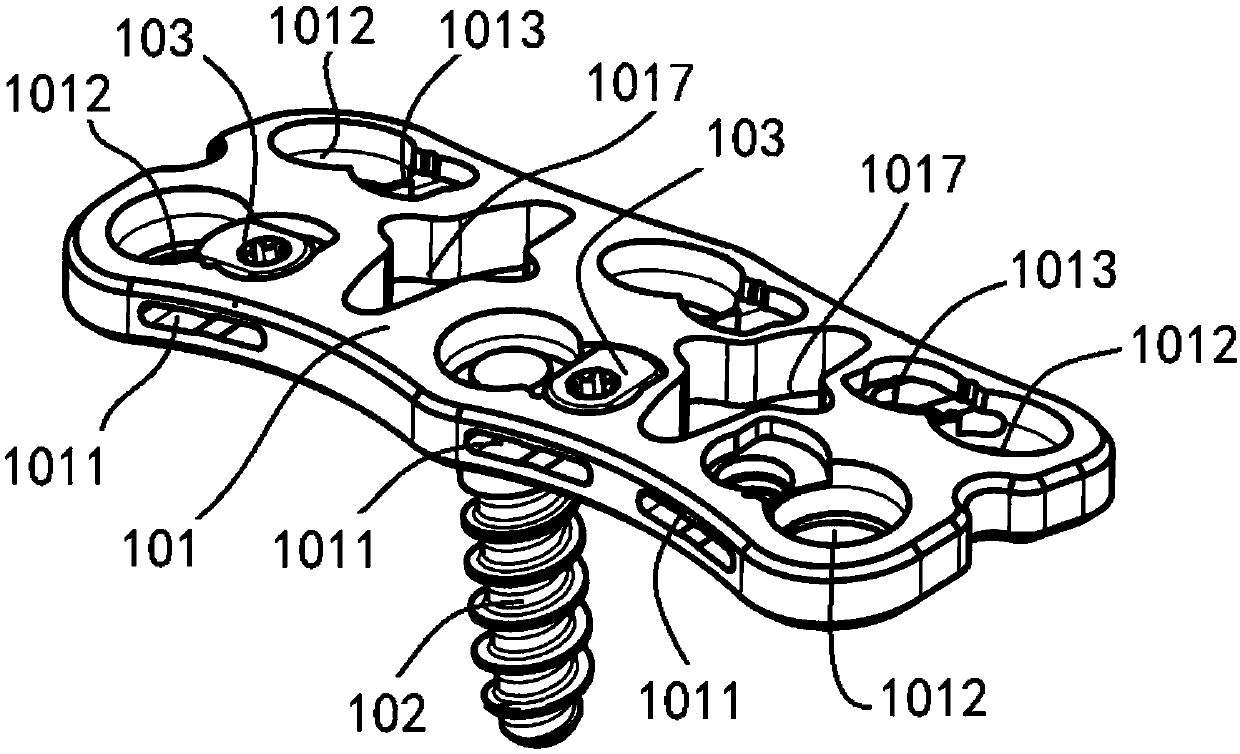
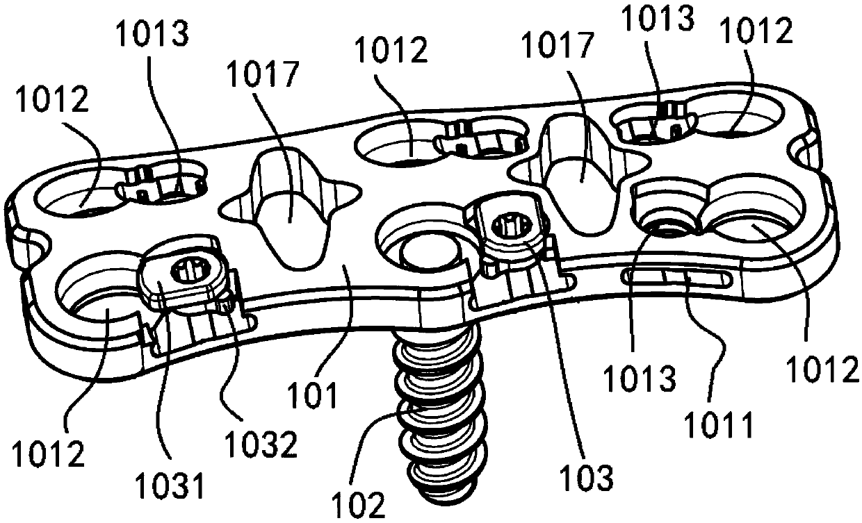
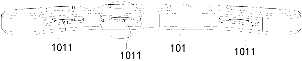
[0041] figure 1 It is a structural diagram of a spinal internal fixation device according to an exemplary embodiment. figure 2 yes figure 1 partial cross-sectional view of figure 2 In particular, it shows the cooperation between the limit part of the anti-off structure and the long hole.

[0042] refer to figure 1 and figure 2 According to one aspect of the present invention, a spinal internal fixation device is provi...


PUM


Abstract

The invention discloses a fixing device in spines. The fixing device includes a device body, screws and anti-dropping structures; the device body is provided with screw holes and long holes; the screwholes penetrate the top surface and bottom surface of the device body; the long holes have top surfaces and bottom surfaces, and the top surfaces and bottom surfaces of the long holes are located between the top surface and bottom surface of the device body; the screws are arranged in the screw holes and can fix the device body on a spine; the anti-dropping structures are rotatably arranged on the device body and have pressing parts and limit parts; the limit parts are movably clamped between the top surfaces and bottom surfaces of the long holes; when the limit parts are located at first positions, the pressing parts can be pressed on the screws so as to make the screws locked in the screw holes; and when the limit parts are located at second positions, the screws are in unlocking states, and the limit parts can be clamped in the long holes, so that the anti-dropping structures can be axially limited. Therefore, the loosening of the anti-dropping structures can be prevented.

Description

technical field [0001] The invention relates to a spinal internal fixation device, in particular to a spinal internal fixation device capable of preventing screws from withdrawing. Background technique [0002] Orthopedic treatment of cervical trauma, degenerative diseases, tumors and spinal instability and other diseases, anterior cervical decompression and interbody fusion is a recognized method for the treatment of cervical spondylosis. Anterior cervical surgery is easy to operate and conducive to postoperative recovery. [0003] In spinal internal fixation surgery, it is necessary to use bone plates and screws to connect the upper and lower vertebral bodies to fix them. Due to the frequent movement of the cervical spine, the screws are prone to loosening and withdrawal after implantation. After withdrawal, it is easy to cause damage to the surrounding soft tissues such as the esophagus, resulting in failure of the implantation. In the prior art, a third member is usual...

Claims


Application Information

Patent Timeline
Patent Type & Authority Applications(China)
IPC IPC(8): A61B17/70A61B17/86
CPCA61B17/70A61B17/7049A61B17/86
Inventor 肖建如吴海源李文钊黄广志董骧徐志华许书富
Owner SHANGHAI CHANGZHENG HOSPITAL
Why Eureka
Try Eureka