Telescopic rail

A technology of telescopic guide rails and guide rails, which is applied in the direction of bearings, shafts and bearings, bearings and other directions of linear motion to achieve the effect of reducing structural requirements

Active Publication Date: 2022-01-11
ACCURIDE INTERNAIONAL GMBH
View PDF16 Cites 0 Cited by
  • Summary
  • Abstract
  • Description
  • Claims
  • Application Information

AI Technical Summary

Problems solved by technology

[0005] It has proven disadvantageous in the prior art that both conventional guideway elements and rolling element cages have to be designed to be movable relative to each other

Method used


Image

  • Telescopic rail
  • Telescopic rail
  • Telescopic rail

Examples


Embodiment Construction

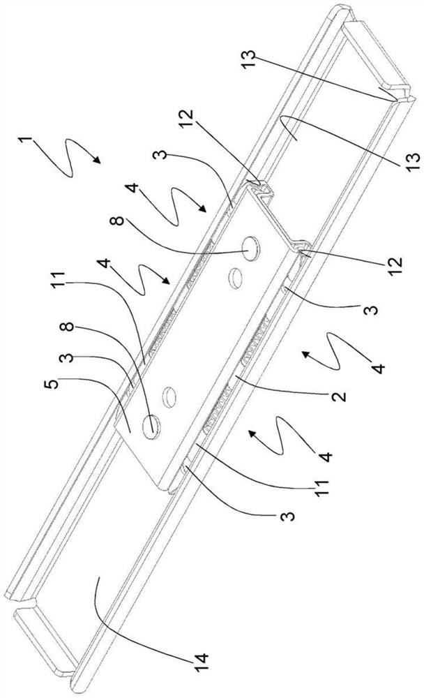
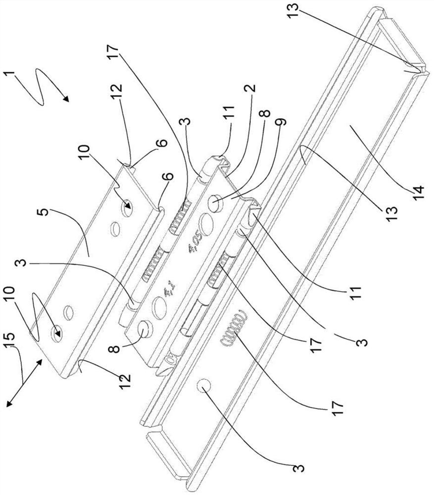
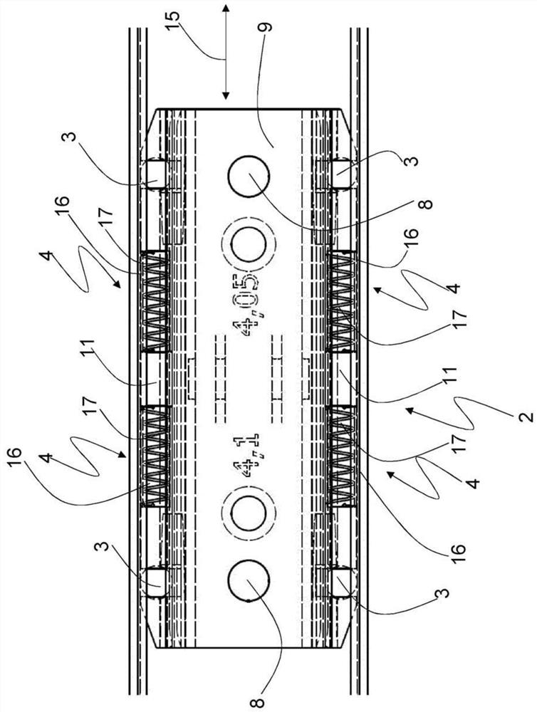
[0041] figure 1 and figure 2 An embodiment of a telescopic guide rail 1 according to the invention is shown, in which a ball cage 2 guides rolling bodies in the form of balls 3 , in addition to which the ball cage is provided with four braking elements 4 . image 3show figure 1 and 2 The ball cage 2 of the telescopic guide rail 1.

[0042] In the illustrated embodiment, the ball cage 2 is fixed to the inner rail 5 . The inner rail 5 thus forms the first rail element according to the application. From figure 2 As can be seen in the exploded view of , the ball cage 2 is clamped into the inner rail 5 such that it extends between the legs 6 of the inner rail 5 which carry the running surface 12 of the inner rail 5 . In order to prevent displacement of the ball cage 2 relative to the inner rail 5, the ball cage 2 has at its connecting portion 9 two protrusions 8 which engage into openings 10 in the inner rail 5, the openings 10 being in contact with the protrusions. Sectio...


PUM


Abstract

The invention relates to a telescopic guide rail comprising: a first guide rail element with two running surfaces; a second guide rail element with two running surfaces; at least one rolling element cage for positioning a plurality of rolling bodies; and a plurality of rolling bodies, which are received at the rolling body cage, wherein the part of the rolling body cage with the rolling bodies is arranged between the running surfaces of the first rail element and the second guide rail element, The first guide rail element and the second guide rail element are linearly displaceable relative to each other along the direction of extension, wherein the rolling body cage establishes the position of each rolling body relative to the rolling body cage along the direction of extension. A disadvantage of such a telescopic guideway is that both the guideway element and the rolling element cage must be designed to be movable relative to one another. Therefore, the present invention proposes a telescopic guideway in which the rolling body cage is fixed to a first guideway element such that the rolling bodies perform a sliding movement relative to the running surface of the first guideway element and the rolling bodies move relative to the second guideway element sliding movement on the running surface of the second rail element or rolling on the running surface of the second guideway element.

Description

technical field [0001] The invention relates to a telescopic guide rail comprising: a first guide rail element with two running surfaces; a second guide rail element with two running surfaces; at least one rolling element cage for positioning a plurality of rolling bodies; and a plurality of rolling bodies, which are received at the rolling body cage, wherein the part of the rolling body cage with the rolling bodies is arranged between the running surfaces of the first rail element and the second guide rail element, The first guide rail element and the second guide rail element are linearly displaceable relative to each other along the direction of extension, wherein the rolling body cage establishes the position of each rolling body relative to the rolling body cage along the direction of extension. Background technique [0002] Telescopic guide rails are known from the prior art with a first guide rail element, a second guide rail element and a rolling body cage, which con...

Claims


Application Information

Patent Timeline
Patent Type & Authority Patents(China)
IPC IPC(8): F16C29/04F16C29/02F16C29/10F16C29/00F16C33/38F16C33/32F16C33/66
CPCF16C2202/52F16C2314/70F16C33/6614F16C29/005F16C29/02F16C29/046F16C29/048F16C33/32F16C33/3806F16C2326/01A47B88/487A47B88/493A47B2210/0035F16C29/04F16C33/38
Inventor C·纽豪斯T·奎莱恩
Owner ACCURIDE INTERNAIONAL GMBH
Why Eureka
Try Eureka