An automatic potting device for potted plants
A technology of equipment and bottom plate, which is applied in the field of automatic depotting equipment, can solve the problems of low depotting efficiency and easy damage of root system of potted plants, and achieve the effect of improving depotting efficiency
- Summary
- Abstract
- Description
- Claims
- Application Information
AI Technical Summary
Problems solved by technology
Method used
Image
Examples
Embodiment 1
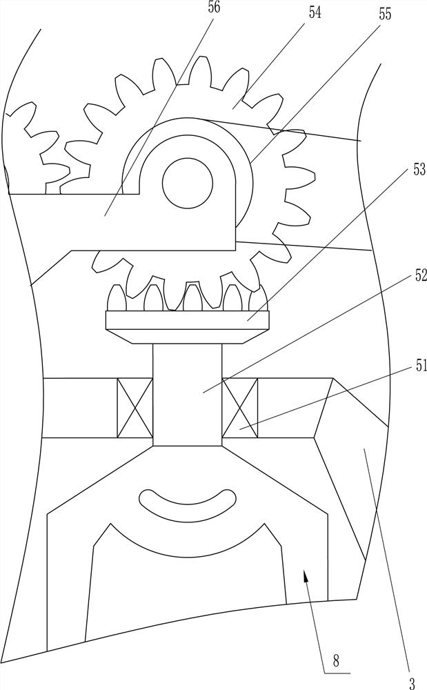
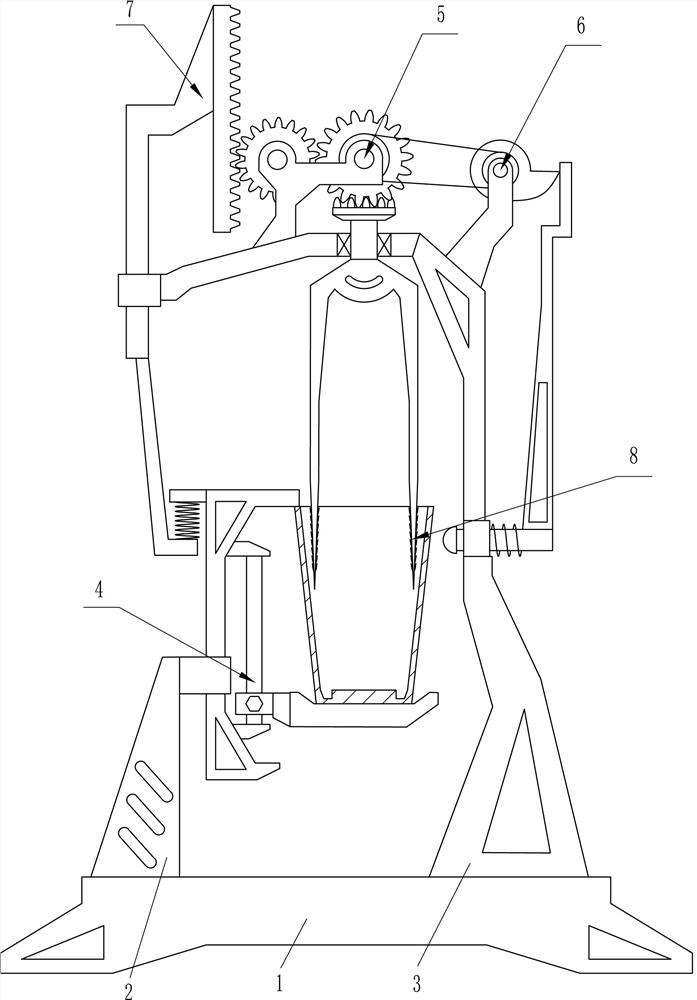
[0026] A potted plant automatic potting device, such as figure 1 As shown, it includes a base plate 1, a first support 2, a second support 3, a carrying device 4, a rotating device 5 and a knocking device 6, the left side of the base plate 1 top is equipped with the first support 2, and the right side of the base plate 1 top The second support 3 is installed, the upper right wall of the first support 2 is equipped with a bearing device 4 , the top of the second support 3 is equipped with a rotating device 5 , and the knocking device 6 is installed on the right wall of the second support 3 .
[0027] When it is necessary to take off the potted plants, the user places the flower pots on the bearing device 4, and then the user starts the rotating device 5 to make the knocking device 6 knock the flower pots, so that the flower pots can be vibrated, so that the potted plants can be carried out. Take off the pot, and can protect the root system of the potted plant from being damaged...
Embodiment 2
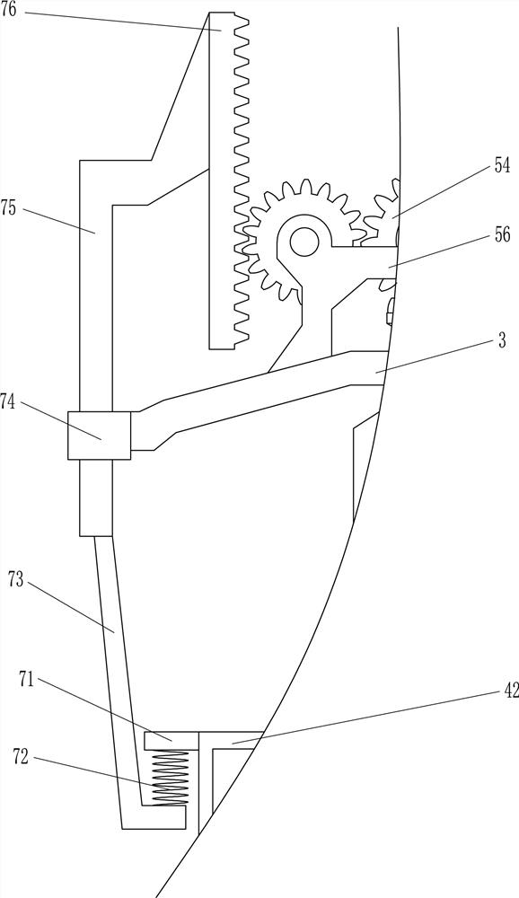
[0035] On the basis of Example 1, such as Figure 6As shown, pressure device 7 is also included, and pressure device 7 includes horizontal plate 71, second spring 72, connecting rod 73, second sliding sleeve 74, second sliding rod 75 and rack 76, and horizontal plate 71 is arranged on the second The left wall upper part of a slide bar 42, the bottom of horizontal plate 71 is equipped with second spring 72, and the bottom end of second spring 72 is fixed with connecting rod 73, and second sliding sleeve 74 is fixed on the left wall of second support 3, and the second The sliding type is provided with the second slide bar 75 in two slide sleeves 74, and the top end of the second slide bar 75 is affixed with the top of connecting rod 73, and the right wall top of the second slide bar 75 is provided with rack 76, and rack 76 Meshes with the first gear 54 on the left.
[0036] Such as Figure 7 As shown, a fixing device 8 is also included. The fixing device 8 includes a pointed c...
PUM
 Abstract
Description
Claims
Application Information
 - R&D
- Intellectual Property
- Life Sciences
- Materials
- Tech Scout
- Unparalleled Data Quality
- Higher Quality Content
- 60% Fewer Hallucinations
Browse by: Latest US Patents, China's latest patents, Technical Efficacy Thesaurus, Application Domain, Technology Topic, Popular Technical Reports.
© 2025 PatSnap. All rights reserved.Legal|Privacy policy|Modern Slavery Act Transparency Statement|Sitemap|About US| Contact US: help@patsnap.com


