Stainless steel flange manufacturing and machining treatment system

A processing system, stainless steel technology, applied in manufacturing tools, metal processing equipment, grinding workpiece supports, etc., can solve the problems of uneven grinding, slow grinding speed, time-consuming and laborious, etc., to improve grinding effect and efficiency, improve efficiency and quality, the effect of reducing the grinding efficiency

Active Publication Date: 2020-07-31
无锡市麒啸机械有限公司
View PDF6 Cites 5 Cited by
  • Summary
  • Abstract
  • Description
  • Claims
  • Application Information

AI Technical Summary

Problems solved by technology

[0003] However, the following problems exist in the grinding of existing stainless steel flanges. a. When grinding traditional flanges, it is generally necessary to manually grind with sandpaper. When grinding by machine, it often causes uneven grinding and slow grinding speed, which reduces the grinding quality of stainless steel flanges and affects the subsequent use of stainless steel flanges; Replacing different grinding heads is a waste of time and low efficiency, and only a single stainless steel flange can be ground, which reduces the grinding efficiency and can improve the efficiency and quality of stainless steel flange grinding

Method used


Image

  • Stainless steel flange manufacturing and machining treatment system
  • Stainless steel flange manufacturing and machining treatment system
  • Stainless steel flange manufacturing and machining treatment system

Examples


Embodiment Construction

[0027] The embodiments of the present invention will be described in detail below with reference to the accompanying drawings, but the present invention can be implemented in many different ways defined and covered by the claims.

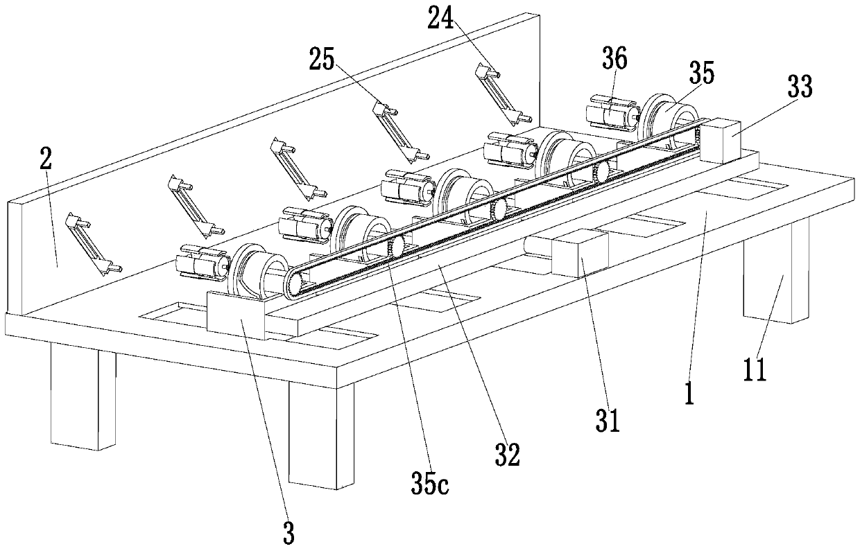
[0028] Such as Figure 1 to Figure 8 As shown, a stainless steel flange manufacturing and processing system includes a base plate 1, a clamping device 2 and a grinding device 3. The clamping device 2 is installed at the rear end of the base plate 1, and the grinding device 3 is installed at the front end of the base plate 1.

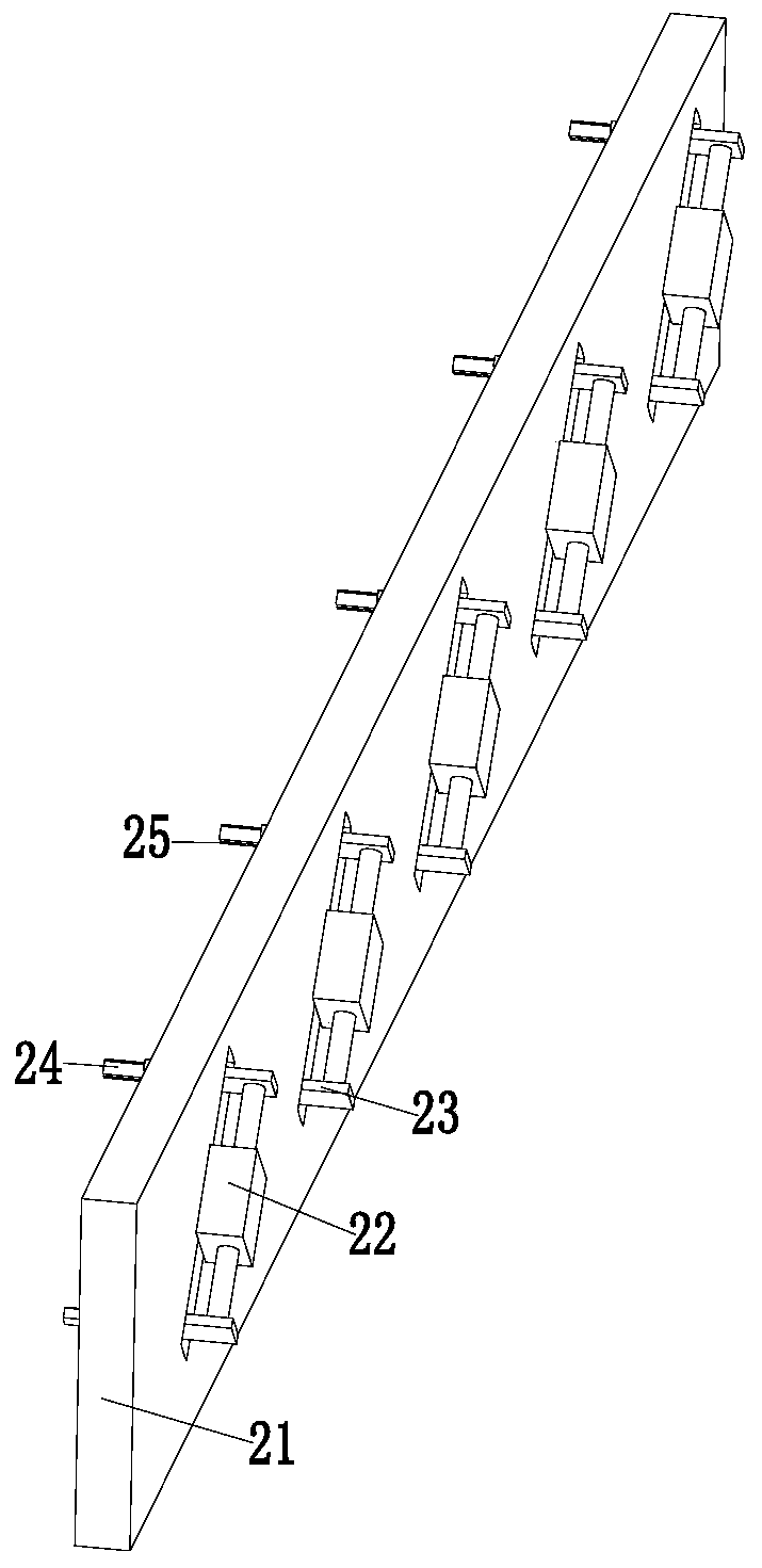
[0029] The clamping device 2 includes a flat plate 21, a two-way cylinder 22, a clamping plate 23, a clamping rod 24 and a rubber plate 25. The rear end of the bottom plate 1 is equipped with a flat plate 21, and the flat plate 21 is evenly opened from the left end to the right end. The chute, the middle end of the chute is equipped with a two-way cylinder 22, the output end of the two-way cylinder 22 is equipped with a clampi...


PUM


Abstract

The invention relates to a stainless steel flange manufacturing and machining treatment system. The stainless steel flange manufacturing and machining treatment system comprises a bottom plate, a clamping device and a polishing device, wherein the clamping device is installed at the rear end of the bottom plate, and the polishing device is installed at the front end of the bottom plate. Accordingto the stainless steel flange manufacturing and machining treatment system, the difficulty problems existing in the stainless steel flange polishing process can be solved, and specifically, a. when atraditional flange is polished, generally, abrasive paper needs to be held manually for polishing, so that polishing wastes time and labor, or a small electric polisher is adopted for polishing and when the small electric polisher is used for the polishing, uneven polishing and low polishing speed are often caused, the polishing quality of the stainless steel flange is reduced, and follow-up use of the stainless steel flange is affected; and b, when an existing stainless steel flange polishing device polishes different stainless steel flanges, different grinding heads need to be replaced, timeis wasted, efficiency is low; and the stainless steel flange manufacturing and machining treatment system can improve stainless steel flange polishing efficiency and quality.

Description

technical field [0001] The invention relates to the technical field of stainless steel processing, in particular to a stainless steel flange manufacturing and processing system. Background technique [0002] Flange is a kind of disc-shaped part, which is the most common in pipeline engineering. Flanges are used in pairs and matched with flanges on valves. Flanges are mainly used for the connection of pipelines. In the pipelines that need to be connected, each installation A piece of flange, and then add flange pads between the two flanges, and finally tighten the two flanges with bolts to make them tightly combined to become a detachable joint, which can realize static pipe to For the connection between rotating or reciprocating equipment, stainless steel flanges need to be polished during the manufacturing process. [0003] However, the following problems exist in the grinding of existing stainless steel flanges. a. When grinding traditional flanges, it is generally necess...

Claims


Application Information

Patent Timeline
Patent Type & Authority Applications(China)
IPC IPC(8): B24B5/36B24B27/00B24B45/00B24B41/06B24B41/02B24B47/06
CPCB24B5/36B24B27/0076B24B41/02B24B41/06B24B45/003B24B47/06
Inventor 赵大为钱昌杰
Owner 无锡市麒啸机械有限公司
Why Eureka
Try Eureka