A quick release hinge

A quick-release, hinged technology, used in construction, door/window fittings, folding panels, etc., can solve problems such as difficult disassembly and inability to hinge, and achieve the effect of convenient cleaning, reducing friction, and avoiding excessive gaps.

Active Publication Date: 2021-08-27
安徽华安六和家居科技有限公司
View PDF0 Cites 0 Cited by
  • Summary
  • Abstract
  • Description
  • Claims
  • Application Information

AI Technical Summary

Problems solved by technology

[0004] The object of the present invention is to provide a quick-release hinge in order to solve the problem that the above-mentioned information hinge cannot be disassembled or is not easy to disassemble.

Method used


Image

  • A quick release hinge
  • A quick release hinge
  • A quick release hinge

Examples


Embodiment 1

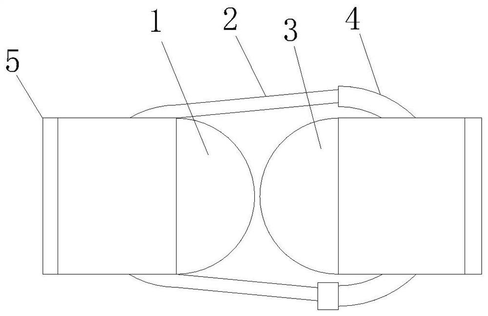
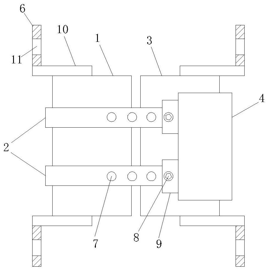
[0029] see Figure 1-3 , a quick-release hinge, including a first cylinder 1, a second cylinder 3 is provided on the right side of the first cylinder 1, and the first cylinder 1 and the second cylinder 3 are installed on the upper and lower sides respectively There is a fixing mechanism 5, and the fixing mechanism 5 includes a connecting rod 10 connected to the first cylinder 1 and the second cylinder 3, a fixing plate 6 is installed on the connecting rod 10, and a fixing hole 11 is provided on the fixing plate 6, so that On the right side of the second cylinder 3, a fixed ring 4 is installed, and a limit brace 2 is installed on the fix ring 4. The limit brace 2 and the fix ring 4 are designed to wrap the first cylinder 1 and the second cylinder 3;

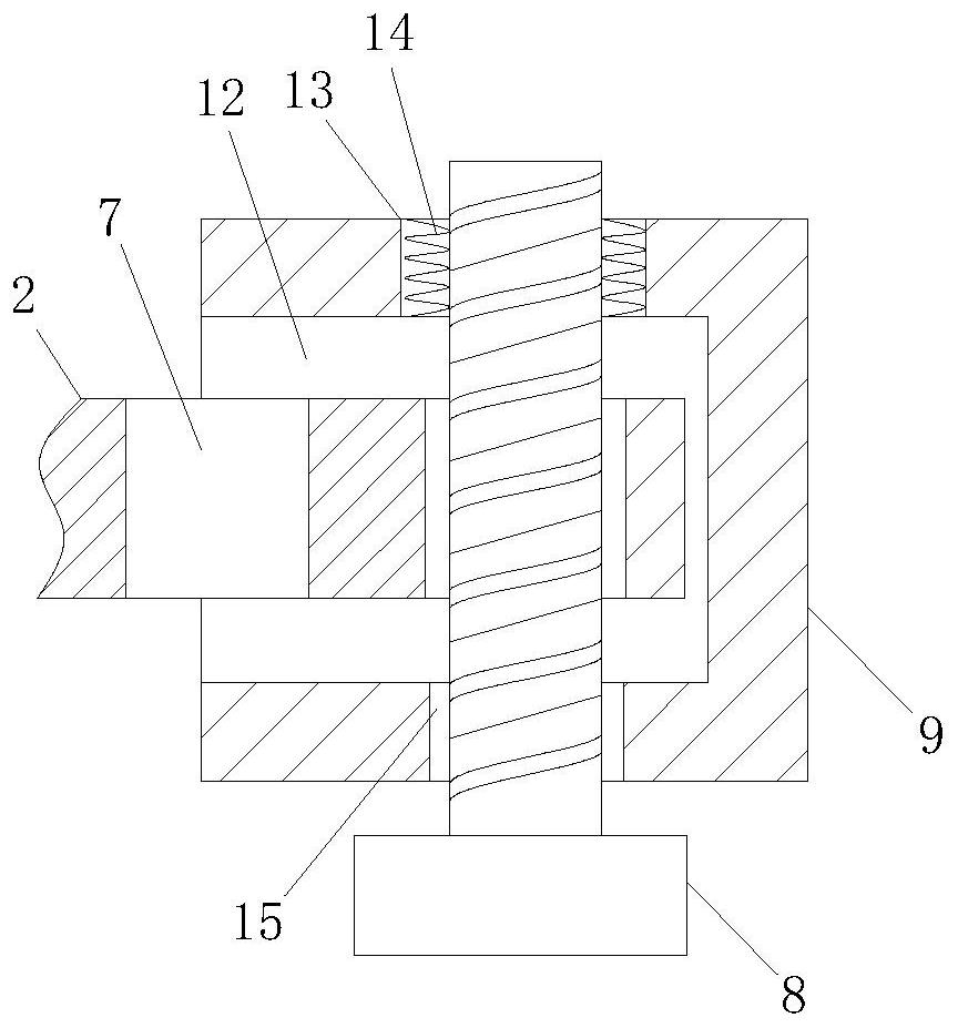
[0030] One end of the limit stay bar 2 is movably connected with the fixed ring 4 through a connector 9, and a through hole 7 is uniformly arranged on the limit stay bar 2, and a corresponding position of the limit stay bar 2 is p...

Embodiment 2

[0033] see Figure 1-4 , a quick-release hinge, including a first cylinder 1, a second cylinder 3 is provided on the right side of the first cylinder 1, and the first cylinder 1 and the second cylinder 3 are installed on the upper and lower sides respectively There is a fixing mechanism 5, and the fixing mechanism 5 includes a connecting rod 10 connected to the first cylinder 1 and the second cylinder 3, a fixing plate 6 is installed on the connecting rod 10, and a fixing hole 11 is provided on the fixing plate 6, so that On the right side of the second cylinder 3, a fixed ring 4 is installed, and a limit brace 2 is installed on the fix ring 4. The limit brace 2 and the fix ring 4 are designed to wrap the first cylinder 1 and the second cylinder 3;

[0034] One end of the limit stay bar 2 is movably connected with the fixed ring 4 through a connector 9, and a through hole 7 is uniformly arranged on the limit stay bar 2, and a corresponding position of the limit stay bar 2 is p...

Embodiment 3

[0037] see Figure 1-5 , a quick-release hinge, including a first cylinder 1, a second cylinder 3 is provided on the right side of the first cylinder 1, and the first cylinder 1 and the second cylinder 3 are installed on the upper and lower sides respectively There is a fixing mechanism 5, and the fixing mechanism 5 includes a connecting rod 10 connected to the first cylinder 1 and the second cylinder 3, a fixing plate 6 is installed on the connecting rod 10, and a fixing hole 11 is provided on the fixing plate 6, so that On the right side of the second cylinder 3, a fixed ring 4 is installed, and a limit brace 2 is installed on the fix ring 4. The limit brace 2 and the fix ring 4 are designed to wrap the first cylinder 1 and the second cylinder 3;

[0038]One end of the limit stay bar 2 is movably connected with the fixed ring 4 through a connector 9, and a through hole 7 is uniformly arranged on the limit stay bar 2, and a corresponding position of the limit stay bar 2 is pr...


PUM


Abstract

The invention discloses a quick-detachable hinge, which comprises a first cylinder, a second cylinder is arranged on the right side of the first cylinder, and the upper and lower sides of the first cylinder and the second cylinder are respectively equipped with fixed mechanism, the fixing mechanism includes a connecting rod connected with the first cylinder and the second cylinder, a fixing plate is installed on the connecting rod, a fixing hole is opened on the fixing plate, and a fixing hole is installed on the right side of the second cylinder. ring, and limit braces are installed on the fixed ring. The invention provides a quick-detachable hinge with ingenious structure and reasonable layout. The design of the ball reduces the friction force when the first cylinder and the second cylinder contact and rotate, so that the door rotates more smoothly and smoothly. Convenient, the first cylinder and the second cylinder made of metal are always in contact with each other through the magnet, so as to avoid the situation that the gap fixed by the limit brace is too large, causing the overturned object such as the door to be displaced and affecting the normal use.

Description

technical field [0001] The invention belongs to the technical field of hinge equipment, in particular to a quick-detachable hinge. Background technique [0002] A hinge, also known as a hinge, is a mechanical device used to connect two solids and allow relative rotation between them. Hinges can be constructed of movable components, or of collapsible material. Hinges are mainly installed on doors and windows, and hinges are more installed on cabinets. According to the classification of materials, they are mainly divided into stainless steel hinges and iron hinges; in order to let people enjoy better, hydraulic hinges (also known as damping hinges) have appeared. Its characteristic is that it brings a buffer function when the cabinet door is closed, which minimizes the noise caused by the collision with the cabinet body when the cabinet door is closed; [0003] Most of the existing hinges are non-detachable, or the structure cannot be installed normally after being disassemb...

Claims


Application Information

Patent Timeline
Patent Type & Authority Patents(China)
IPC IPC(8): E05D7/12E05D11/02E05D11/04
CPCE05D7/12E05D7/123E05D11/02E05D11/04
Inventor 冯伯成
Owner 安徽华安六和家居科技有限公司
Why Eureka
Try Eureka