Sapling watering device used for garden

A technology for watering devices and saplings, which is applied in the directions of watering devices, gardening, applications, etc., can solve the problems of reducing watering efficiency, increasing the workload of workers, and different growth conditions of small saplings.

Inactive Publication Date: 2020-08-04
宋娟利
View PDF6 Cites 2 Cited by
  • Summary
  • Abstract
  • Description
  • Claims
  • Application Information

AI Technical Summary

Problems solved by technology

[0003] In order to protect the greening of the garden, some small saplings need to be planted in the garden every year for this reason, to provide convenience for the landscaping. At present, after the small saplings are planted in the garden, workers are required to water the small saplings. Because each small sapling is watered The amount of water is different, which will cause the growth of each small sapli

Method used


Image

  • Sapling watering device used for garden
  • Sapling watering device used for garden
  • Sapling watering device used for garden

Examples


Embodiment 1

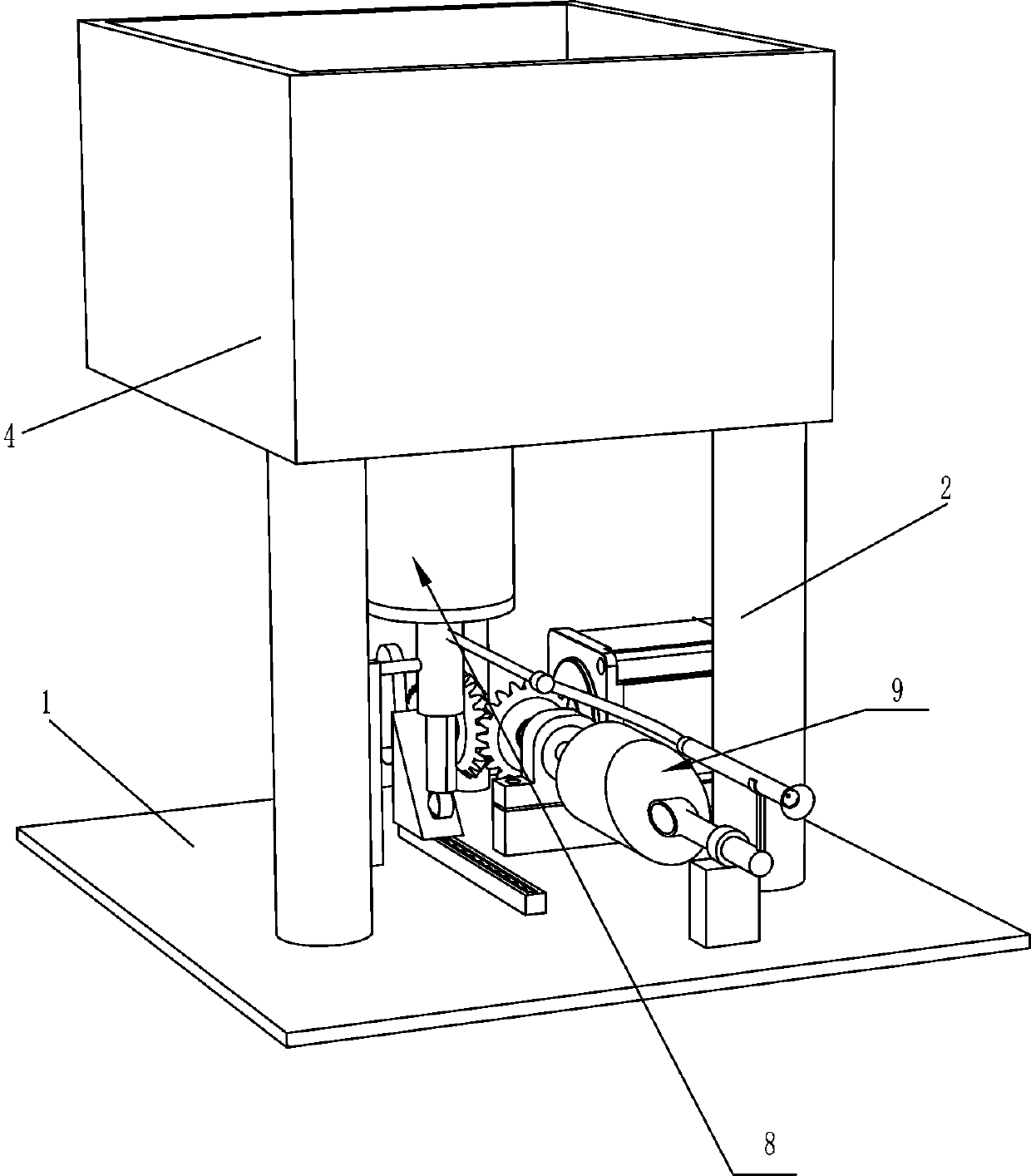
[0022] A kind of small sapling watering device for garden, such as figure 1 , figure 2 and image 3 As shown, it includes a bottom plate 1, a first pillar 2, a second pillar 3, a water tank 4, a rotating rod 5, a baffle plate 6, a driving mechanism 7 and a water intake mechanism 8, and the top of the bottom plate 1 is connected with two first pillars 2, Second pillar 3 is installed on the bottom plate 1 of first pillar 2 front sides, and water tank 4 is fixedly connected between the top of first pillar 2 and second pillar 3, and the bottom of water tank 4 is rotatably equipped with rotating rod 5, and rotating rod 5 is connected with a baffle plate 6, the drive mechanism 7 is installed on the bottom plate 1 on the left side of the second pillar 3, and the water intake mechanism 8 is arranged on the bottom plate 1 on the right side of the drive mechanism 7.

[0023] When the present invention needs to be used, the user adds an appropriate amount of water into the water tank ...

Embodiment 2

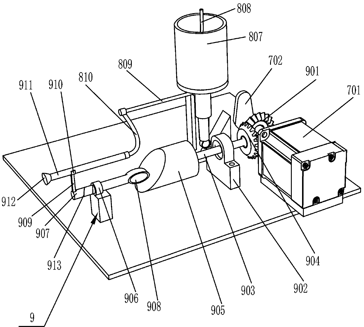
[0025] On the basis of Example 1, as Figure 4 and Figure 5 As shown, the driving mechanism 7 includes a reduction motor 701, a cam 702, a slide rail 703, a slider 704, a first spring 705 and a first wedge block 706, and the reduction motor 701 is installed on the bottom plate 1 on the left side of the second pillar 3 by bolts. On the output shaft of the geared motor 701, a cam 702 is installed, and the slide rail 703 is arranged on the bottom plate 1 on the right side of the geared motor 701 through bolts. The slide rail 703 is slidably provided with a slide block 704, and the slide block 704 and the slide rail 703 A first spring 705 is connected between them, and a first wedge block 706 is fixed on the top of the slider 704 .

[0026] like Figure 4-7 As shown, the water intake mechanism 8 includes a support 801, a hollow pipe 802, a delivery pipe 803, a moving rod 805, a contact wheel 806, a water intake bucket 807, a connecting rod 808, a water outlet pipe 809 and a fle...

Embodiment 3

[0030] On the basis of Example 2, such as Figure 7 As shown, it also includes a mobile spraying mechanism 9, and the mobile spraying mechanism 9 includes a first bevel gear 901, a bearing seat 902, a rotating shaft 903, a second bevel gear 904, a second wedge block 905, a sliding sleeve 906, a slide bar 907, Contact block 908, pole 909, ferrule 910, water spray pipe 911, nozzle 912 and second spring 913, first bevel gear 901 is installed on the output shaft of reduction motor 701 on the left side of cam 702, and bearing seat 902 is installed on the output shaft of reduction motor 702. On the bottom plate 1 at the right rear of the motor 701, a rotating shaft 903 is installed in the bearing seat 902, and a second bevel gear 904 is installed on one end of the rotating shaft 903, and the second bevel gear 904 meshes with the first bevel gear 901, and the other end of the rotating shaft 903 is equipped with a The second wedge block 905, a sliding sleeve 906 is installed on the ba...


PUM


Abstract

The invention relates to a sapling watering device, in particular to a sapling watering device used for a garden. The invention aims to solve the technical problem of supplying a way of providing thesapling watering device used for a garden, and the sapling watering device can lower a workload and can improve watering efficiency. The sapling watering device used for the garden comprises a bottomplate, first supporting columns, a second supporting column, a water tank, a rotary rod, a baffle plate and the like, wherein the top of the bottom plate is connected with two first supporting columns; the bottom plate, which is far away from the first supporting columns, is provided with the second supporting column; the water tank is fixedly connected among the top ends of the first supporting columns and the second supporting column; the bottom of the water tank is rotatably provided with the rotary rod; and the rotary rod is connected with the baffle plate. Through a driving mechanism, a water fetching mechanism can fetch water in the water tank, through the water fetching mechanism, water for watering saplings can be quantified, so that a user can conveniently water the sapling so asto lower the workload of the user, and in addition, sapling water efficiency can be improved.

Description

technical field [0001] The invention relates to a small sapling watering device, in particular to a small sapling watering device for gardens. Background technique [0002] Using engineering technology and artistic means in a certain area to create a beautiful natural environment and recreational environment by transforming the terrain (or further building mountains, stacking stones, and water management), planting trees and flowers, building buildings, and arranging garden roads, etc. It's called a garden. [0003] In order to protect the greening of the garden, some small saplings need to be planted in the garden every year for this reason, to provide convenience for the landscaping. At present, after the small saplings are planted in the garden, workers are required to water the small saplings. Because each small sapling is watered The amount of water is different, which will cause the growth of each small sapling to be different. In order to facilitate the management of...

Claims


Application Information

Patent Timeline
IPC IPC(8): A01G25/02A01G29/00
CPCA01G25/02A01G29/00
Inventor 宋娟利
Owner 宋娟利
Why Eureka
Try Eureka