Mesh insert pin core-pulling induction die structure

A technology of inserting needles and mesh holes is applied in the field of core-pulling induction mold structures for mesh inserting needles. The effect of product strain and accurate mold opening

Pending Publication Date: 2020-08-04
TAIDEXING PRECISE ELECTRON KUSN
View PDF0 Cites 1 Cited by
  • Summary
  • Abstract
  • Description
  • Claims
  • Application Information

AI Technical Summary

Problems solved by technology

For the deep hole structure on the side wall, it is necessary to use the insert pin to penetrate the deep hole position, and use the slider to exit the side wall position. In the existing slider structure, the inclined guide post is used to delay the mold opening, and wait until the insert position is completely withdrawn. , the slider can be separated; this structure cannot detect whether the insert is completely pulled out in place during the whole production process, and the wrong time for the slider to withdraw will cause product strain
This structure relies on high-precision parts matching. When the matching accuracy of products or parts is not in place, the push-out time of the slider cannot be controlled, resulting in defective products

Method used


Image

  • Mesh insert pin core-pulling induction die structure
  • Mesh insert pin core-pulling induction die structure

Examples


Embodiment

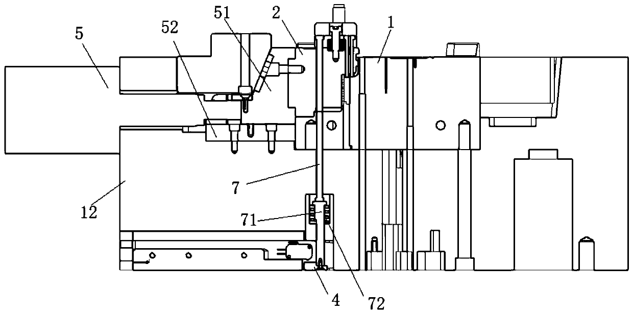
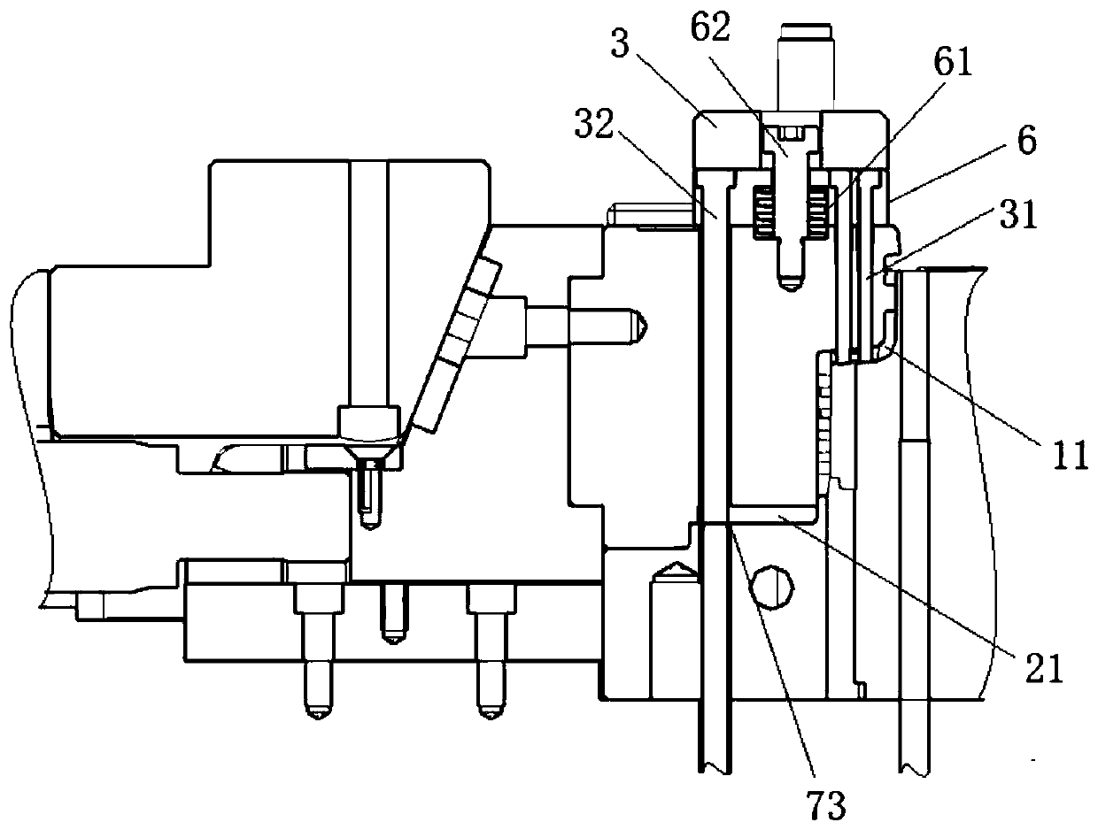
[0020] refer to Figure 1-2 As shown, this embodiment is a mesh inlaid needle core-pulling induction mold structure, including a lower mold core 1, a slider 2 that abuts against the side of the lower mold core 1 to form a cavity 11, and is movable on the slider 2. The pin fixing plate 3 on the top, the connecting pin fixing plate 3 extending through the slider 2 to the pin 31 in the cavity 11, the connecting rod 32 that moves relatively synchronously with the setting pin 31, and the sensor corresponding to the end of the connecting rod 32 4. And the induction cylinder 5 which is arranged on the side of the slider 2 and drives the slider 2 to withdraw from the cavity 11; the sensor 4 transmits the movement signal of the connecting rod 32 to the induction cylinder 5 through the injection molding machine (not shown).

[0021] The lower mold core 1 is set in the lower template 12, an arc-shaped cavity 11 is formed between the upper side of the lower mold core 1 and the slider 2, a...


PUM


Abstract

The invention discloses a mesh insert pin core-pulling induction die structure. The structure comprises a lower die core, a sliding block, an insert pin fixing plate, an insert pin, a connecting rod,a sensor and a sensing oil cylinder, wherein the sliding block and the side of the lower die core are in corresponding butt joint to form a cavity; the insert pin fixing plate is movably arranged on the top of the sliding block, the insert pin is connected to the insert pin fixing plate and penetrates through the sliding block to extend into the cavity, the connecting rod synchronously moves relative to the insert pin, the sensor corresponds to the tail end of the connecting rod, and the sensing oil cylinder is arranged on the side of the sliding block and drives the sliding block to retreat from the cavity. The sensor transmits a moving signal of the connecting rod to the sensing oil cylinder through an injection molding machine. According to the structure, the time when the sliding blockretreats is accurately controlled, and forming of a mold opening product is precisely controlled.

Description

technical field [0001] The invention belongs to the technical field of moulds, and in particular relates to a mesh-studded needle core-pulling induction mold structure. Background technique [0002] For appearance products, the surface needs to be scratched. For the deep hole structure on the side wall, it is necessary to use the insert pin to penetrate the deep hole position, and use the slider to exit the side wall position. In the existing slider structure, the inclined guide post is used to delay the mold opening, and wait until the insert position is completely withdrawn. Only when the slider is separated can the slider be separated; it is impossible to detect whether the insert is completely pulled out in place during the whole production of this structure, and the wrong time for the slider to withdraw will cause the product to be strained. This structure relies on high-precision parts matching. When the matching accuracy of products or parts is not in place, the push...

Claims


Application Information

Patent Timeline
Patent Type & Authority Applications(China)
IPC IPC(8): B29C45/33B29C45/80
CPCB29C45/33B29C45/80
Inventor 郝金刚胡志伟
Owner TAIDEXING PRECISE ELECTRON KUSN
Why Eureka
Try Eureka