Self-hole-aligning coupler and using method thereof

A technology of couplings and inner holes, which is applied in the field of self-aligning couplings, can solve the problems of difficult assembly and low efficiency of couplings, reduce installation process costs, enhance reliability and compactness, and prolong service life The effect of longevity

Pending Publication Date: 2022-05-27
中铝西南铝板带有限公司
View PDF0 Cites 0 Cited by
  • Summary
  • Abstract
  • Description
  • Claims
  • Application Information

AI Technical Summary

Problems solved by technology

[0005] The present invention intends to provide a self-aligning hole coupling to solve the problems...

Method used


Image

  • Self-hole-aligning coupler and using method thereof
  • Self-hole-aligning coupler and using method thereof
  • Self-hole-aligning coupler and using method thereof

Examples


Embodiment

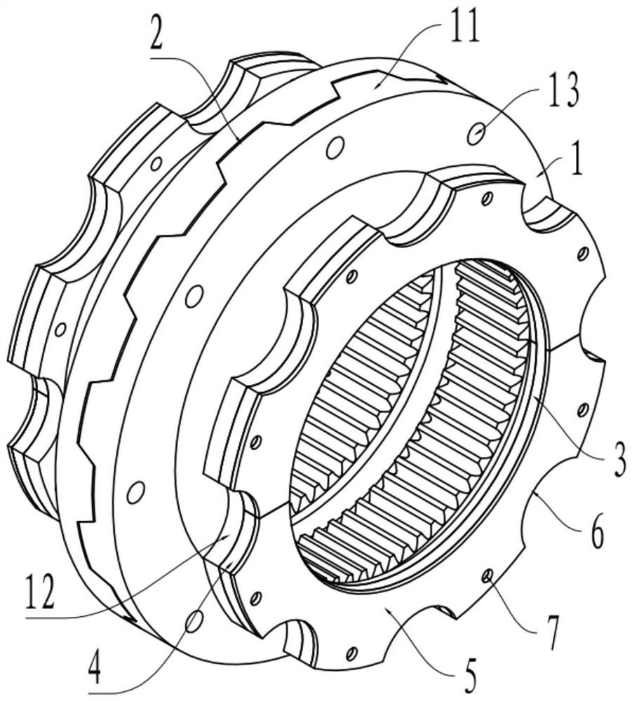
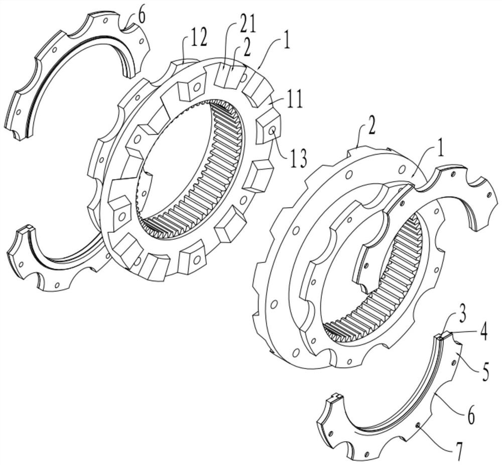
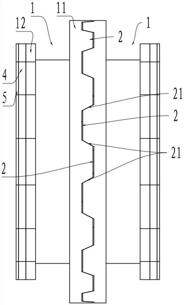
[0041] The embodiment is basically as attached Figure 1 to Figure 4 As shown, a self-aligning hole coupling includes two symmetrical connecting sleeves 1, and the inner hole of each connecting sleeve 1 is formed with mating teeth connected with the connecting shaft (the mating teeth can be in the form of splines or In the form of an inner ring gear, this embodiment adopts the form of an inner ring gear, wherein the connecting shaft has teeth meshing with the mating teeth), and the two ends of each connecting sleeve 1 are integrally formed with a flange one 11 and a flange two 12, Flange 11 is formed with a plurality of protrusions 2 uniformly distributed along the circumference of the connecting sleeve 1, and each protrusion 2 is formed with a symmetrical inclined guide surface 21, and the guide surfaces 21 on the two connecting sleeves 1 can offset each other. A depression for accommodating the protrusion 2 on the other connecting sleeve 1 is formed between adjacent protrusi...


PUM


Abstract

The invention relates to the technical field of connecting parts, in particular to a self-hole-aligning coupler and a using method thereof.The self-hole-aligning coupler comprises two connecting sleeves, each connecting sleeve is provided with a plurality of protrusions evenly distributed in the circumferential direction of the connecting sleeve, each protrusion is provided with a guide face, and the guide faces on the two connecting sleeves can abut against each other; a recess for accommodating the bulge on the other connecting sleeve is formed between the adjacent bulges on the same connecting sleeve; when the coupling is used, the connecting sleeve is firstly connected with the connecting shaft; then the protrusion of one connecting sleeve is matched with the recess of the other connecting sleeve, butt joint of the two connecting sleeves is completed through sliding of the connecting sleeves along the guide faces, and finally bolts penetrate through the connecting holes to achieve fixed connection of the two connecting sleeves. The scheme is used for solving the problems of high assembly difficulty and low efficiency in the disassembly and assembly of the coupler in the prior art.

Description

technical field [0001] The invention relates to the technical field of connecting parts, in particular to a self-aligning hole coupling and a method for using the same. Background technique [0002] In the prior art, the shaft coupling is widely used in the connection of the shafts of two different machines (the shafts of the two machines are hereinafter referred to as connecting shafts). The shaft coupling includes two detachably connected connecting sleeves. When connecting the connecting shafts, one of the connecting sleeves is connected with one connecting shaft, the other connecting sleeve is connected with the other connecting shaft, and then the two connecting sleeves are connected, that is, the connection of the two connecting shafts is realized, ensuring that the two A connecting shaft and coupling act synchronously. [0003] When the connecting shaft needs to be replaced frequently, the connecting sleeve of the coupling often needs to be disassembled, but most of ...

Claims


Application Information

Patent Timeline
IPC IPC(8): F16D1/033F16D1/06
CPCF16D1/033F16D1/06Y02E10/72
Inventor 何智力吴雷殷雷陈俊阳彭闯
Owner 中铝西南铝板带有限公司
Why Eureka
Try Eureka