
Gas-liquid two-phase washing suction nozzle and sanitation vehicle

A sanitation vehicle, gas-liquid technology, applied in the direction of road cleaning, cleaning methods, construction, etc., can solve problems such as the decline in the cleaning effect, the impact of the volume of the garbage bin, and the residual water on the ground, so as to achieve a complete garbage push effect and ensure cleaning The effect of sweeping normal operation and reducing the use of water resources

Active Publication Date: 2020-08-04
ZHENGZHOU YUTONG HEAVY IND
View PDF8 Cites 2 Cited by
  • Summary
  • Abstract
  • Description
  • Claims
  • Application Information

AI Technical Summary

Problems solved by technology

However, this cleaning operation mode also has the following problems: 1) It needs to consume a lot of water, which is not suitable for cities in the north where there is a drought and water shortage. The water after washing the ground will be sucked into the suction nozzle like garbage, which becomes a suction burden ;2) In order to hold more clean water, the volume of the garbage bin is affected; 3) After the operation, there is a lot of residual water on the ground, which cannot be used in winter, and the ground is frozen; 4) When the high-pressure nozzle is blocked, the effect of cleaning operation will decrease obvious

Method used


Image

  • Gas-liquid two-phase washing suction nozzle and sanitation vehicle
  • Gas-liquid two-phase washing suction nozzle and sanitation vehicle
  • Gas-liquid two-phase washing suction nozzle and sanitation vehicle

Examples


Embodiment Construction

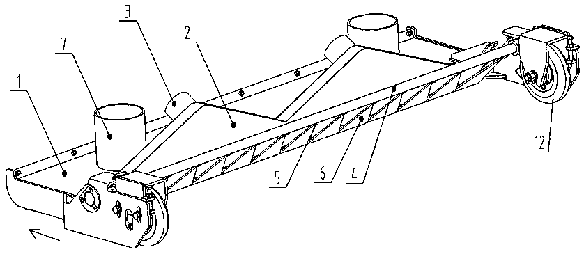
[0028] In the present invention, the walking direction of the sanitation vehicle is taken as the front, and vice versa. The walking direction of the sanitation vehicle is as follows: figure 1 in the direction of the arrow.

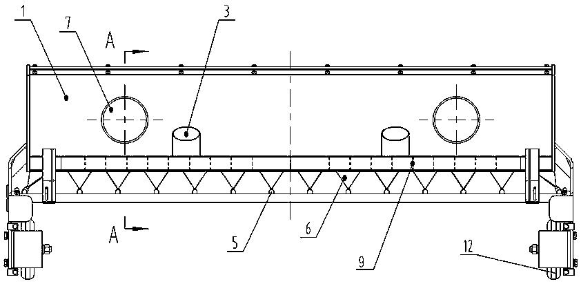
[0029] like Figure 1-5 As shown, a gas-liquid two-phase flushing nozzle includes a nozzle body 1, a suction pipe 7 and a high-pressure spray gun 4 are welded on the upper surface of the nozzle body 1, and the lower side of the high-pressure spray gun 4 is installed at intervals along its axial direction The high-pressure nozzle 5 of the front injection, the air intake duct 2 is arranged between the suction pipe 7 and the high-pressure spray gun 4, the upper end of the air intake duct 2 is welded with the air intake duct 3, and the lower end passes through the nozzle body 1 and extends into the Inside the cavity of the nozzle body 1.

[0030] In order to prevent the larger garbage from blocking the air intake duct 2 and the high-pressure nozzle 5, and to...


PUM


Abstract

The invention discloses a gas-liquid two-phase washing suction nozzle and a sanitation vehicle. The gas-liquid two-phase washing suction nozzle comprises a nozzle body. A suction pipe and a high-pressure spray gun are welded to the upper surface of the nozzle body, high-pressure spraying nozzles spraying forwards are installed on the lower side face of the high-pressure spray gun at intervals in the axial direction, an air inlet duct is arranged between the suction pipe and the high-pressure spray gun, an air inlet pipe is welded to the upper end of the air inlet duct, and the lower end of theair inlet duct penetrates through the nozzle body and extends into a cavity of the nozzle body. A vertical abrasion-resistant block is arranged between the suction pipe and the air inlet duct, the top end of the abrasion-resistant block is connected to the nozzle body, a gap is reserved between the bottom end of the abrasion-resistant block and the ground, and the edge of the rear portion of theabrasion-resistant block is connected with the front bottom end of the air inlet duct. The extending end of the air inlet duct is in a flat shape inclining forwards, the section of the extending end of the air inlet duct is gradually decreased in the outlet direction, and the width of the extending end of the air inlet duct is consistent with the suction width of the suction nozzle. Compared withthe prior art, the gas-liquid two-phase washing suction nozzle has the following advantages: garbage is flushed through a high-speed air curtain and a water curtain, so that the water consumption canbe reduced, and the cleaning rate and the operation stability are improved.

Description

technical field [0001] The invention belongs to a suction nozzle structure for a sanitation vehicle, in particular to a gas-liquid two-phase flushing nozzle and a sanitation vehicle, which are applied to sanitation vehicles or equipment for road cleaning. Background technique [0002] With the rapid development of urban and rural construction, the scope of urban roads, suburban roads and township roads continues to expand. As people have higher and higher requirements for environmental cleanliness, the pressure and workload of road cleaning are also increasing accordingly. In order to achieve efficient and fast cleaning operations and reduce labor costs, the demand for sanitation vehicles and equipment for road cleaning is growing rapidly. According to the needs of the market and customers, the industry has continuously launched various sanitation sweeper products with various functions and stable performance. How to improve the operation effect of sanitation sweeper and dev...

Claims


Application Information

Patent Timeline
Patent Type & Authority Applications(China)
IPC IPC(8): E01H1/10E01H1/08
CPCE01H1/101E01H1/0818
Inventor 徐浩张喆杨庆海魏茂亚谢兵阳于志强马迎坤黄帅帅
Owner ZHENGZHOU YUTONG HEAVY IND
Learn More