Pump body of vortex type self-priming electric pump and pumping method thereof

A self-priming and vortex technology, which is applied to parts of pumping devices for elastic fluids, non-variable pumps, pumps, etc., can solve the problems of unsatisfactory suction effect and poor gas discharge effect, and achieve ideal pumping Suction effect, large head effect

Pending Publication Date: 2020-08-04
TAIZHOU PROUDUN ELECTROMECHANICAL CO LTD
View PDF0 Cites 2 Cited by
  • Summary
  • Abstract
  • Description
  • Claims
  • Application Information

AI Technical Summary

Problems solved by technology

[0003] Aiming at the problems of poor gas discharge effect and unsatisfactory suction effect of existing vortex pumps, the present invention provides a pump body of a vortex self-priming electric pump and a pumping method thereof. The gas can be discharged in time, the suction effect is ideal, and the pumping method can be obtained. Large head

Method used


Image

  • Pump body of vortex type self-priming electric pump and pumping method thereof
  • Pump body of vortex type self-priming electric pump and pumping method thereof
  • Pump body of vortex type self-priming electric pump and pumping method thereof

Examples


Embodiment 1

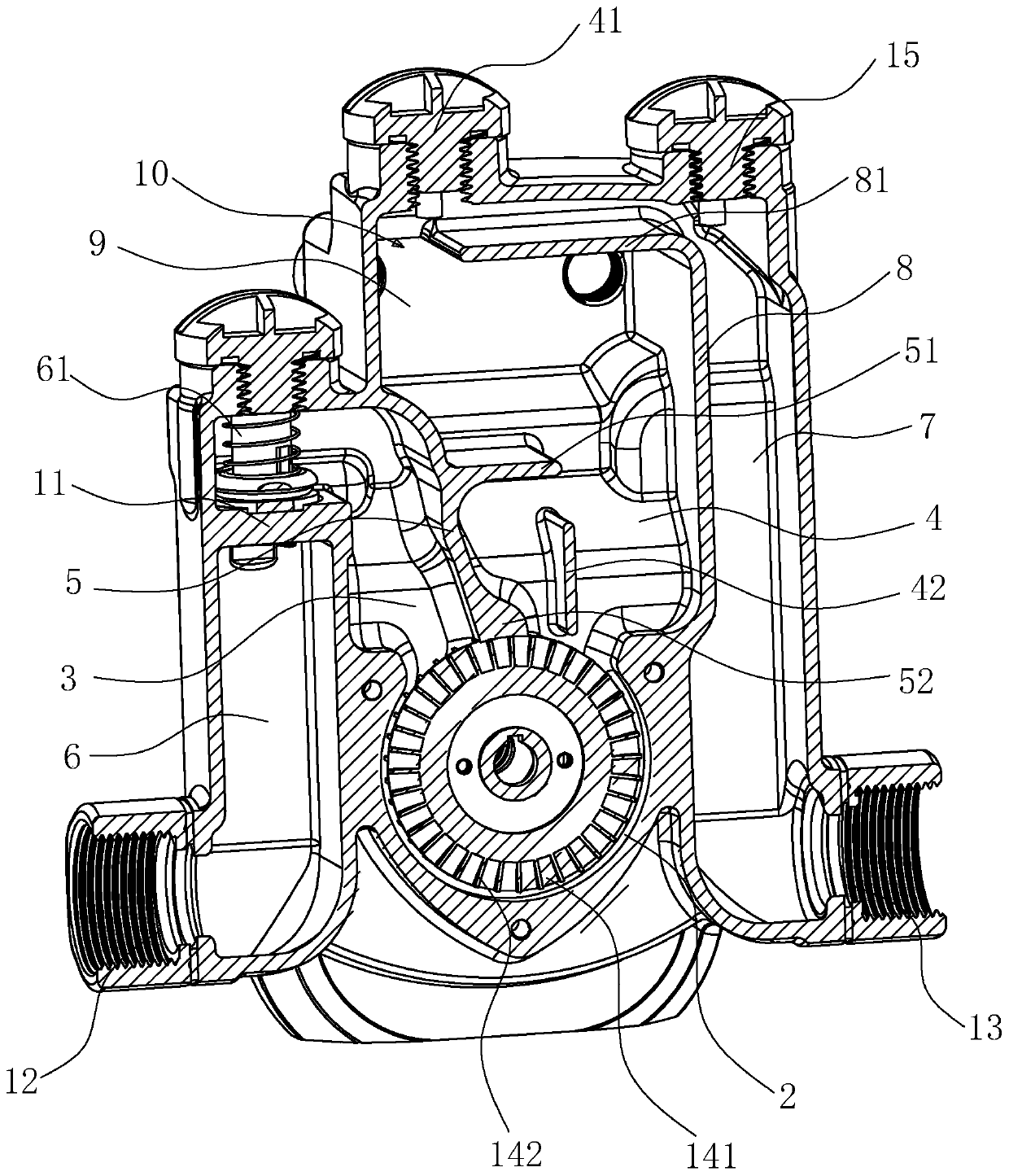
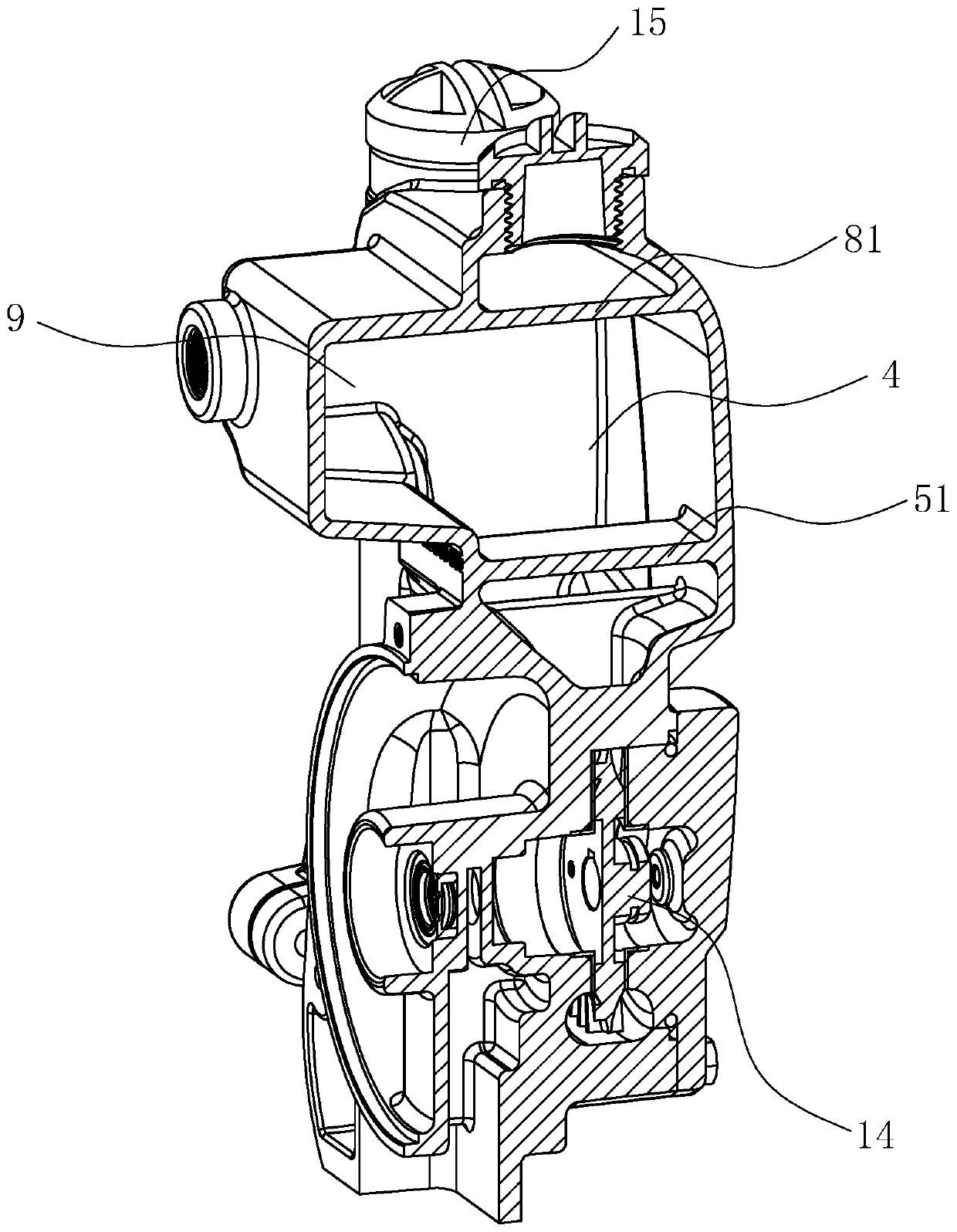
[0034] The pump body of the vortex type self-priming electric pump of the present embodiment, as Figure 2 to Figure 3As shown, it includes a casing 1 and is arranged in the casing 1: a vortex chamber 2 for accommodating the impeller 14, and a water inlet volute 3 and an air-water separation chamber 4 communicated with the vortex chamber 2; the water inlet volute 3 The air-water separation chamber 4 is separated by the compartment wall 5, the water inlet chamber 6 communicates with the water inlet spiral cavity 3, the water outlet chamber 7 communicates with the air-water separation chamber 4, and the water filling port 41 is arranged in the air-water separation chamber 4, in order to pour fluid into the air-water separation chamber 4, a first partition wall 8 is provided between the water outlet chamber 7 and the air-water separation chamber 4, and one end of the first baffle plate 81 is arranged on the first partition wall. On the upper part of the partition wall 8, the othe...

Embodiment 2

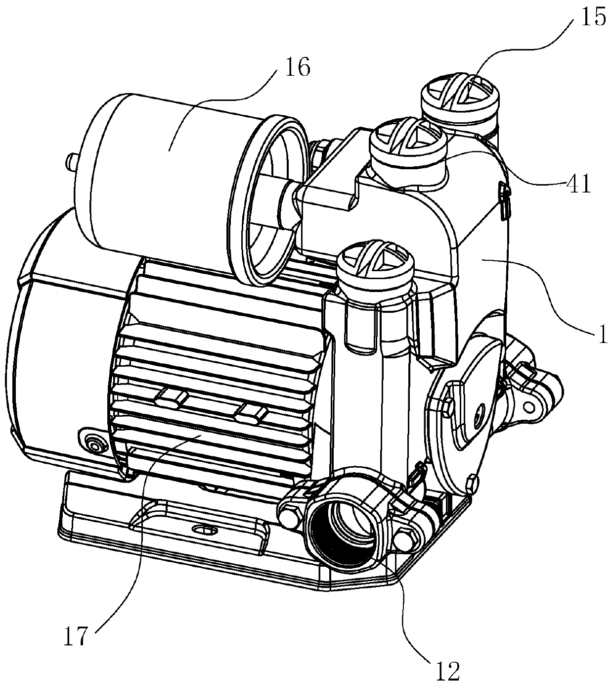
[0045] Such as figure 1 As shown, a vortex self-priming electric pump includes a pressure tank 16, a motor 17 and the pump body of Embodiment 1.

Embodiment 3

[0047] The method of pumping fluid by using the pump body of the vortex self-priming electric pump, the vortex self-priming electric pump used is the vortex self-priming electric pump of embodiment 2, the pump body is the pump body of embodiment 1, and the specific details of the pump body The structure includes an outer shell 1 and the following in the outer shell 1:

[0048] The impeller 14 is provided with a plurality of blades 141, and there is a gap 142 between adjacent blades 141;

[0049] The vortex cavity 2 is used to accommodate the impeller 14;

[0050] The water inlet volute chamber 3 and the air-water separation chamber 4 communicate with the vortex chamber 2;

[0051] The water inlet chamber 6 is connected to the water inlet 12 at one end and connected to the water inlet volute chamber 3 at the other end;

[0052] The water outlet chamber 7 is connected to the first water outlet 13 at one end and the gas-water separation chamber 4 at the other end;

[0053] The...


PUM


Abstract

The invention relates to a pump body of a vortex type self-priming electric pump and a pumping method thereof, and belongs to the field of electric pumps to solve the problems that an existing vortexpump is poor in gas exhaust effect and not ideal in pumping effect. According to the technical scheme, the pump body of the vortex pump comprises a shell, an eddy cavity, a water inlet volute cavity and a gas-water separation chamber, wherein the eddy cavity, the water inlet volute cavity and the gas-water separation chamber are formed in the shell; the water inlet volute cavity and the gas-waterseparation chamber are separated by a separation cavity wall, a water filling port is formed in the top of the gas-water separation chamber, a first partition wall is arranged between a water outlet cavity and the gas-water separation chamber, one end of a first baffle is arranged on the upper portion of the first partition wall, and the other end of the first baffle transversely extends to the separation cavity wall; a notch is formed below the water filling port and used for blocking fluid, so that a part of the fluid flows back into the eddy cavity, and gas follows the other part of the fluid to enter the water outlet cavity through the notch. The invention provides a method for pumping the fluid through the pump body. Part of the fluid falls back under the blocking action of the firstbaffle, the negative pressure effect can be utilized all the time, the pumping effect of the pump body is ideal, and large lift can be obtained.

Description

technical field [0001] The invention belongs to the field of electric pumps, in particular to a pump body of a vortex type self-priming electric pump and a pumping method thereof. Background technique [0002] The existing vortex pump has a pump body, a frequency converter, a pressure tank and a motor. The pump body is provided with a water inlet and a water outlet, and the axes of the water inlet and the water outlet are on the same straight line. The electrical connection of the motor is used to control the operation of the motor. The drive shaft of the motor is connected to the impeller to drive the impeller to rotate. The frequency converter can control the opening and closing of the motor and adjust the speed of the motor. The pressure tank stabilizes the internal pressure of the pump body during the process. During use, the impeller rotates to accelerate the fluid and push it from the water inlet to the water outlet to obtain the lift. Fill the pump body with water be...

Claims


Application Information

Patent Timeline
IPC IPC(8): F04D13/06F04D9/02F04D29/44
CPCF04D9/02F04D13/06F04D29/428F04D29/441
Inventor 周神文沈云荣王涛
Owner TAIZHOU PROUDUN ELECTROMECHANICAL CO LTD
Why Eureka
Try Eureka