Knee joint structure

A knee joint and push rod technology, applied in the field of knee joint structure of prosthetic users, can solve the problems of inconvenient adjustment of elastic body strength, easy to exceed critical angle, easy to fall and get injured, etc.

Active Publication Date: 2020-08-07
KEN DALL ENTERPRISE
View PDF7 Cites 0 Cited by
  • Summary
  • Abstract
  • Description
  • Claims
  • Application Information

AI Technical Summary

Problems solved by technology

[0004] see Figure 16 to Figure 18 , because the reset device 921 is set on the knee joint body 92, and the protrusion 931 is set on the connecting rod 93, the critical angle of knee joint bending is only about 60°~80° due to the transformation of the axis point during the knee joint movement. (like Figure 16 ), but its actual use when walking is: when the knee joint is walking fast, the bending angle easily exceeds the critical angle, causing the knee joint that should return to the straight state to continue bending unexpectedly (such as Figure 17 The bending direction of the knee joint, the arro...

Method used


Image

  • Knee joint structure
  • Knee joint structure
  • Knee joint structure

Examples


Embodiment Construction

[0045] The following is a detailed description based on specific embodiments and drawings.

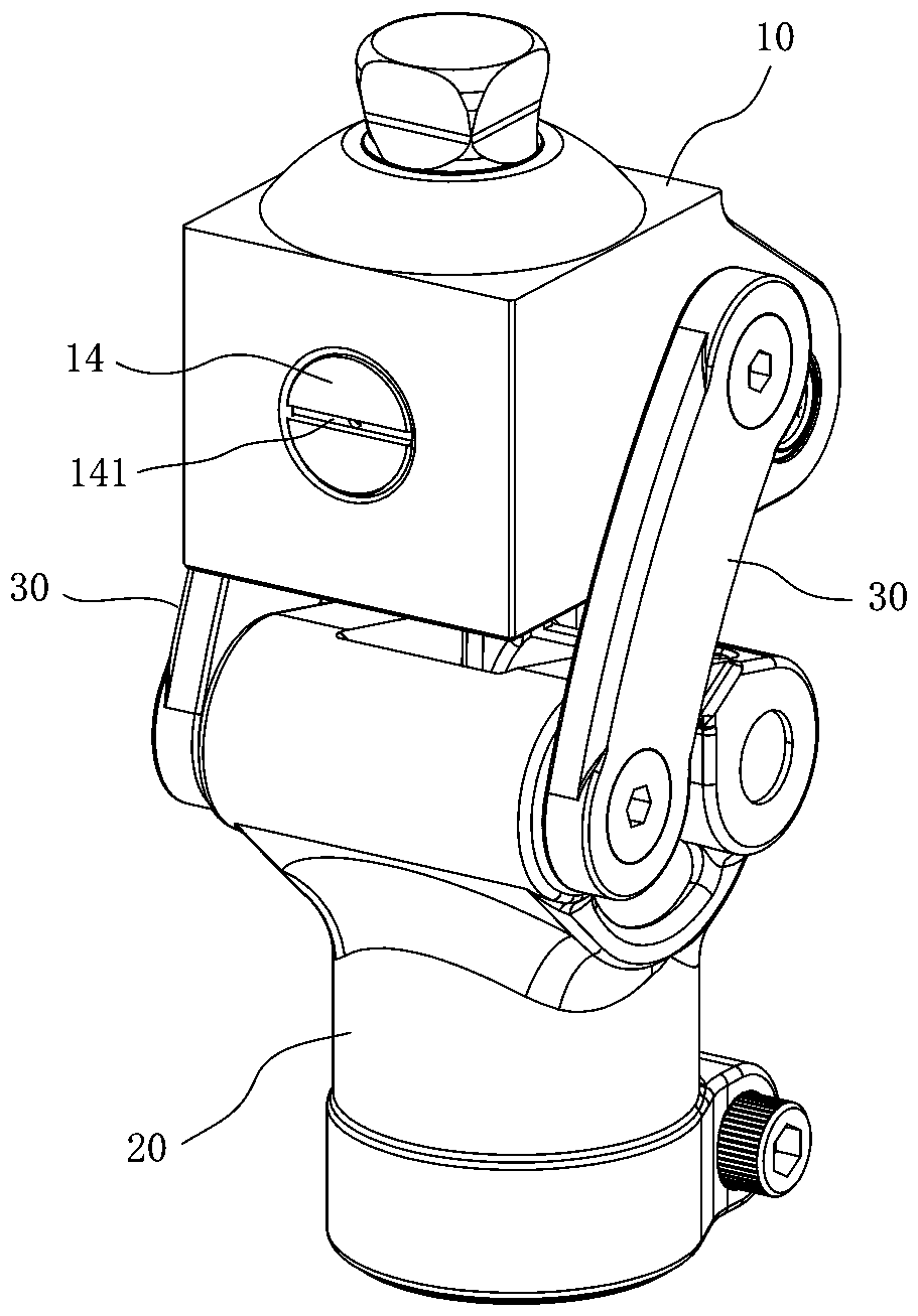
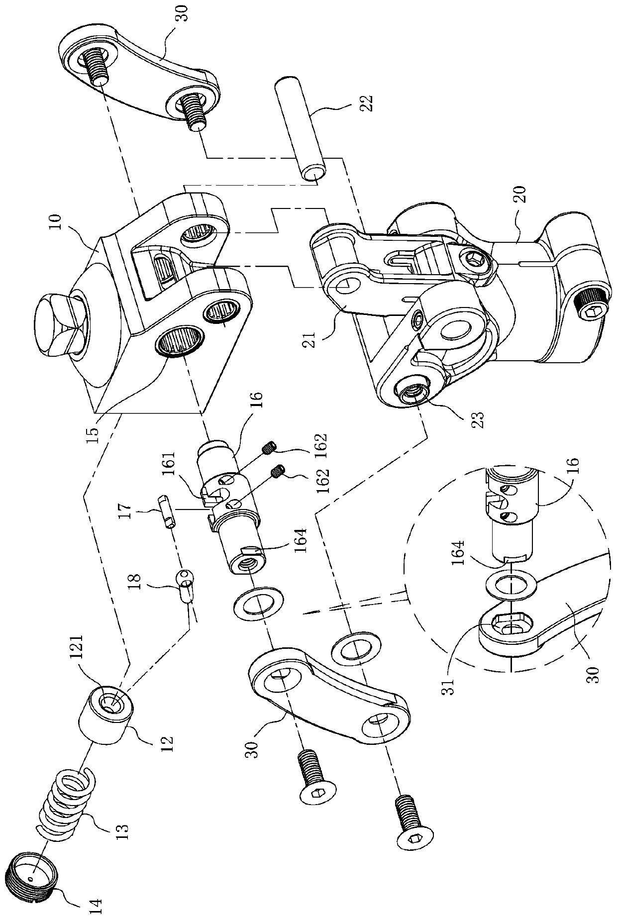
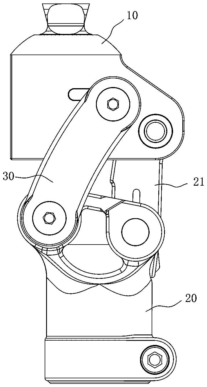
[0046] see Figure 1 to Figure 6 , the present invention comprises a knee joint head 10, a knee joint body 20, and two arc pieces 30. It will be explained in detail below:

[0047] The knee joint head 10 has a reset hole 11, and the reset hole 11 has a piston 12, an elastic body 13, and an adjustment cover 14, and the two ends of the elastic body 13 are respectively against the piston 12, the adjustment cover 14, and Knee joint head 10 has a shaft hole 15, and this shaft hole 15 is provided with a transmission shaft 16, and this transmission shaft 16 has a breach 161, and this breach 161 establishes a push rod shaft 17, and this push rod shaft 17 pivotally connects one and can promote this. Push rod 18 of piston 12 .

[0048] The knee joint body 20 has a connecting rod 21 , one end of the connecting rod 21 is pivotally connected to the knee joint head 10 via a first axis 22 , and th...


PUM


Abstract

The invention relates to a knee joint structure. The knee joint structure comprises a knee joint head, a knee joint body and at least one arc part, the knee joint head is provided with a reset devicecomposed of a piston, an elastic body and an adjusting cover and a transmission shaft, the transmission shaft is provided with a push rod shaft, the push rod shaft is pivoted with a push rod capable of pushing the piston, and the knee joint body is pivoted with the knee joint head through a connecting rod. When the knee joint is bent, the push rod can push the elastic body to store elastic force,and returns to the original shape through the elastic force of the elastic body when the knee joint reversely pivots. The reset device and the push rod are arranged on the knee joint head. The critical angle of knee joint bending can be larger than the bending angle during walking; normal walking gait can be completed in each step, the defect that in the prior art, the knee joint exceeds a critical angle after being bent, and consequently the knee joint which should be straightened originally continues to be bent unexpectedly and is prone to falling down and being injured is overcome, safety can be improved, and the strength of the elastic body can be adjusted conveniently to be matched with the walking speed of a user.

Description

technical field [0001] The present invention relates to a knee joint structure, in particular to a knee joint structure for prosthesis users that can increase walking safety, facilitate adjustment of joint recovery strength, and save walking effort. Background technique [0002] Prosthetic limbs mainly refer to artificial limbs, which are used to replace the functions of disabled limbs, or to modify the appearance of disabled limbs. Among them, the knee joint is the key to the design, because it is related to the gait and mechanical balance during walking and must have Replace the support and walking functions of the normal knee joint. [0003] Conventional knee structures, see Figure 15 , Figure 16 , mainly comprising a knee joint head 91, a knee joint body 92, and a connecting rod 93 and an arc 94 for connecting the knee joint head 91 and the knee joint body 92, wherein the knee joint body 92 is provided with a reset device 921, and the connecting rod 93 is provided wi...

Claims


Application Information

Patent Timeline
IPC IPC(8): A61F2/38
CPCA61F2/3836Y02A50/30
Inventor 郑嘉宝梁智炫吴祥铭
Owner KEN DALL ENTERPRISE
Why Eureka
Try Eureka