
Bamboo shoot shredding device for making sour bamboo shoot shreds

A technology for cutting shreds and bamboo shoots, applied in the direction of using tools for cleaning, cleaning methods and utensils, chemical instruments and methods, etc., can solve problems such as inapplicability and inability to clean shredded blades, and achieve the effect of keeping clean

Active Publication Date: 2020-08-07
安徽爱德葡萄深加工有限公司
View PDF7 Cites 7 Cited by
  • Summary
  • Abstract
  • Description
  • Claims
  • Application Information

AI Technical Summary

Problems solved by technology

[0005] In order to overcome the shortcomings that the current method of shredding bamboo shoots cannot clean the shredding blades and is not suitable for shredding a large number of bamboo shoots, the technical problem to be solved is to provide a method that can clean the shredding blades and is suitable for use with bamboo shoots. Bamboo shoot shredding device for making shredded sour bamboo shoots with a large number of bamboo shoots

Method used


Image

  • Bamboo shoot shredding device for making sour bamboo shoot shreds
  • Bamboo shoot shredding device for making sour bamboo shoot shreds
  • Bamboo shoot shredding device for making sour bamboo shoot shreds

Examples


Embodiment 1

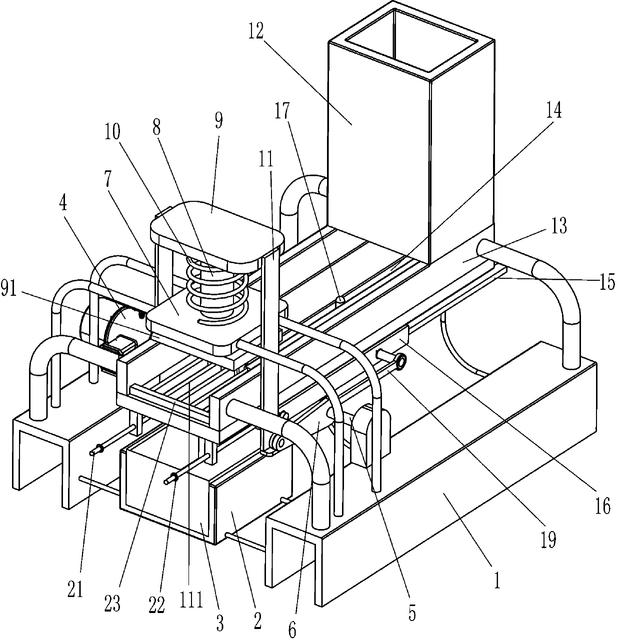
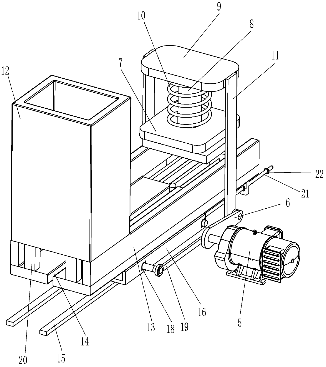
[0018] A kind of bamboo shoot shredding device that sour bamboo shoot shreds is made, such as Figure 1-3 As shown, it includes a base 1, a placement frame 2, a collection frame 3, a shredded assembly and a discharge assembly. The inner front side of the base 1 is fixed with a placement frame 2 by bolts, and the collection frame 3 is placed in the placement frame 2. The base 1 The front portion is provided with a shred assembly that provides power for lifting and shredding by a motor, and the rear portion of the base 1 is provided with a discharge assembly for discharging and shredding bamboo shoots by sliding.

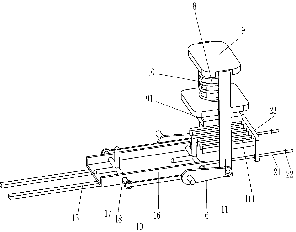
[0019] Such as Figure 1-3 As shown, the shredding assembly includes a reduction motor 4, a rotating shaft 5, a bump 6, a mounting plate 7, a slide bar 8, a connecting plate 9, a pressing plate 91, a compression spring 10, an L-shaped plate 11 and a knife net 111, and the reduction motor 4 is fixed on the front left side of the base 1 through bolts, the rotating shaf...

Embodiment 2

[0025] On the basis of Example 1, such as figure 2 As shown, a limiting plate 20 is also included, and the limiting plate 20 is welded symmetrically to the left and right of the rear side of the guide plate 13 .

[0026] Such as Figure 1-3 Shown, also include slide bar 21, stop block 22 and wiping block 23, slide bar 16 front side is welded with slide bar 21 symmetrically left and right, slide bar 21 fronts are all provided with two stop blocks 22, stop block 22 A wiper block 23 is slidably provided on the sliding bar 21 between them, and the wiper block 23 cooperates with the knife net 111 .

[0027] The working principle of the above-mentioned embodiment: the limiting plate 20 has a limiting function, so as to prevent the bamboo shoots from being pushed away by the push rod 17 .

[0028] When the slide plate 16 moves backward, it drives the slide bar 21 to move backward, and then drives the stop block 22 on the front side to move backward. When the stop block 22 on the f...


PUM


Abstract

The invention relates to a shredding device, in particular to a bamboo shoot shredding device for making sour bamboo shoot shreds. The bamboo shoot shredding device aims to solve the technical problemof how to provide a bamboo shoot shredding device for making the sour bamboo shoot shreds, wherein the bamboo shoot shredding device can clean shredding blades and is suitable for shredding a large number of bamboo shoots. The bamboo shoot shredding device for making the sour bamboo shoot shreds comprises a base, a placing frame, a collecting frame, a shredding assembly and a discharging assembly, wherein the placing frame is mounted on the base, the collecting frame is placed in the placing frame, the shredding assembly is mounted on the base, lifting shredding is conducted through power provided by a motor, the discharging assembly is installed on the base, and the bamboo shoots are discharged and shredded in a sliding mode. According to the bamboo shoot shredding device, through the shredding assembly and the discharging assembly, the effect that cut blocks move downwards combines with the effect that the bamboo shoots are pushed to move to the position above a cutter net, so thatthe effect of automatically shredding the bamboo shoots is achieved; limiting plates have limiting functions, so that the bamboo shoots are prevented from being pushed away by push rods; and limitingblocks can drive a wiping block to repeatedly move front and back, and the cutter net can be automatically cleaned.

Description

technical field [0001] The invention relates to a shredding device, in particular to a bamboo shoot shredding device for making sour bamboo shoot shreds. Background technique [0002] Sour bamboo shoots are a delicacy made with bamboo shoots and salt as the main ingredients. When making shredded sour bamboo shoots, the bamboo shoots need to be cut into shreds. [0003] The patent authorization announcement number is CN209335699U, which discloses a high-efficiency bamboo shoot shredding machine, including an operating table, and the front and rear edges, left side, middle and right sides of the upper end of the operating table are respectively provided with a chute, a finished product groove, and an operating area. and the placement area, the upper left side of the operation area is evenly equipped with a shredding guide, the right end of the shredding guide is provided with an unloading groove, and the left and right ends of the inside of the shredding guide are respectivel...

Claims


Application Information

Patent Timeline
IPC IPC(8): B26D1/03B26D7/06B26D7/08B08B1/00
CPCB26D1/03B26D7/0608B26D7/088B08B1/143
Inventor 侯郁有
Owner 安徽爱德葡萄深加工有限公司
Learn More