Engine combustion chamber

A combustion chamber and engine technology, applied in combustion chambers, continuous combustion chambers, machines/engines, etc., can solve problems such as failure of electric nozzles, avoid failure to install, and improve service life

Active Publication Date: 2020-08-07
AECC HUNAN AVIATION POWERPLANT RES INST
View PDF12 Cites 2 Cited by
  • Summary
  • Abstract
  • Description
  • Claims
  • Application Information

AI Technical Summary

Problems solved by technology

The electric nozzles of the ignition structure in the prior art often wear out due to factors such as vibration and thermal compensation sliding after being used for a period of time, resulting in premature failure of the electric nozzles

Method used


Image

  • Engine combustion chamber
  • Engine combustion chamber
  • Engine combustion chamber

Examples


Embodiment Construction

[0055] Example embodiments will now be described more fully with reference to the accompanying drawings. Example embodiments may, however, be embodied in many forms and should not be construed as limited to the embodiments set forth herein; rather, these embodiments are provided so that this disclosure will be thorough and complete, and will fully convey the concept of example embodiments to those skilled in the art. The same reference numerals in the drawings denote the same or similar structures, and thus their detailed descriptions will be omitted.

[0056] Although relative terms such as "upper" and "lower" are used in this specification to describe the relative relationship of one component of an icon to another component, these terms are used in this specification only for convenience, for example, according to the drawings Directions for the example described. It will be appreciated that if the illustrated device is turned over so that it is upside down, then elements...


PUM


Abstract

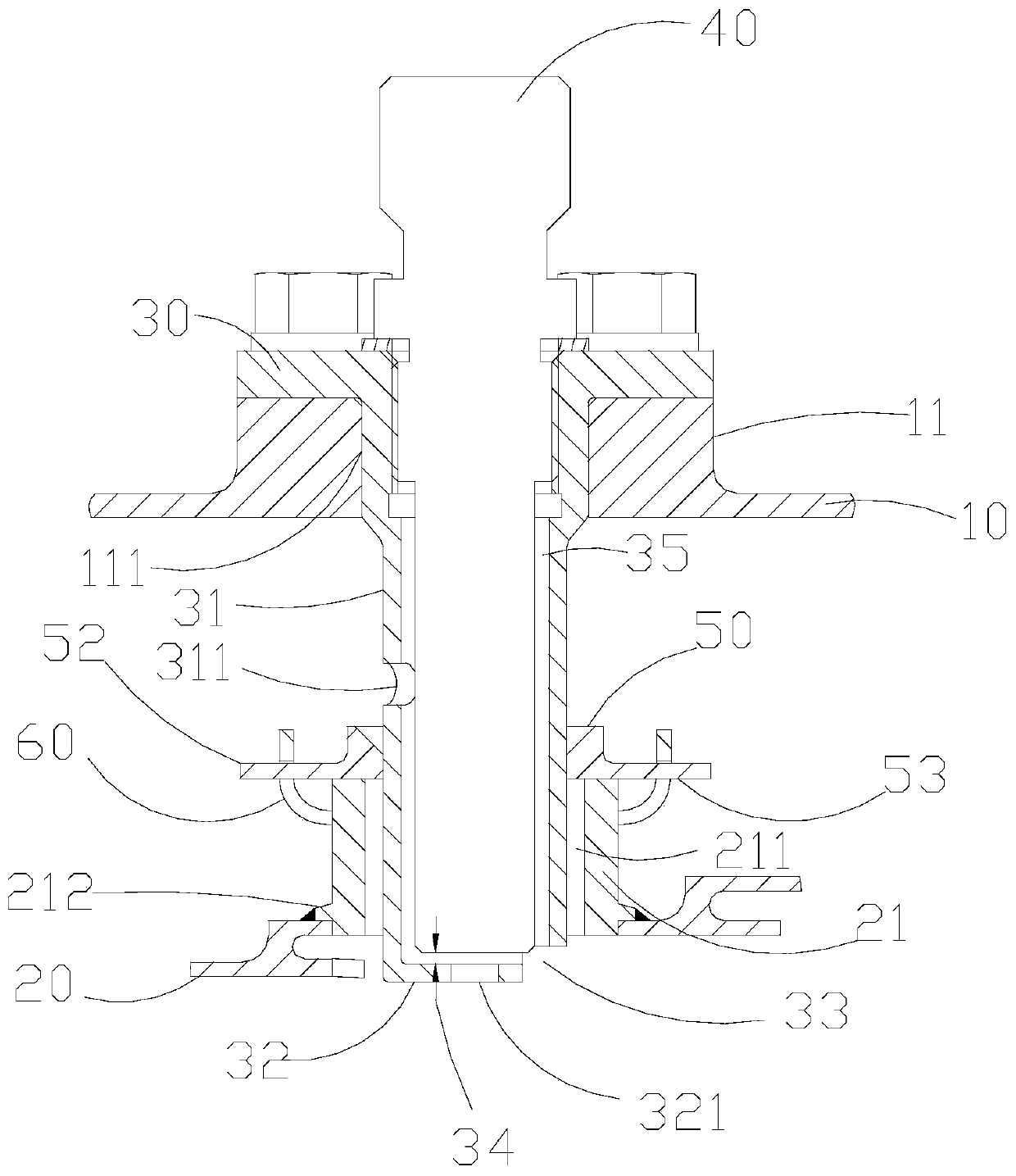
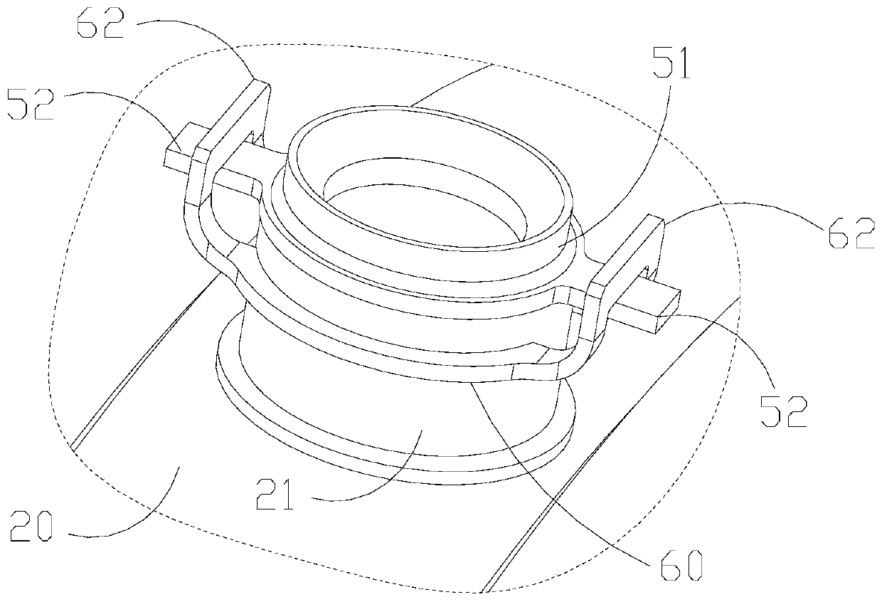
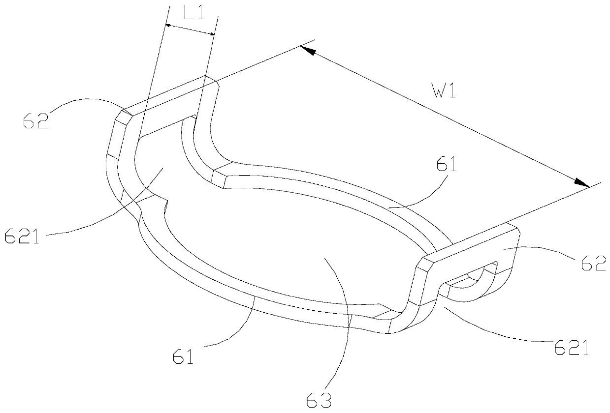
The invention provides an engine combustion chamber. The engine combustion chamber comprises a casing, a flame tube, a sleeve, an ignition plug and a bushing, the casing is provided with a first mounting seat, and the first mounting seat is provided with a first middle hole; the flame tube is provided with a second mounting seat, and the second mounting seat is provided with a second middle hole;the sleeve is mounted on the first mounting seat and extends from the first middle hole to the second middle hole; at least part of the ignition plug is arranged in the sleeve and is fixedly connectedwith the sleeve; and the bushing sleeves the periphery of the sleeve and is movably connected to the second mounting seat.

Description

technical field [0001] The present invention generally relates to the technical field of engines, and in particular, relates to an engine combustion chamber. Background technique [0002] Ignition performance is an important indicator to measure the engine combustion chamber. The factors affecting the ignition performance of the combustion chamber are not only related to the aerodynamic design performance of the combustion chamber itself and the working environment during ignition, but also related to the design of the ignition structure. The electric mouth of the ignition structure in the prior art is often worn out due to factors such as vibration and thermal compensation sliding after being used for a period of time, resulting in premature failure of the electric mouth. Contents of the invention [0003] A main purpose of the present invention is to provide an engine combustion chamber in which the nozzle is not easy to wear. [0004] In order to realize the above-men...

Claims


Application Information

Patent Timeline
IPC IPC(8): F02K9/95F02K9/00F23R3/42
CPCF02K9/00F02K9/95F23R3/42
Inventor 彭中九陈丕敏张卓娅罗莲军陈盛蔡茂张德宝蒋尧吴良成
Owner AECC HUNAN AVIATION POWERPLANT RES INST
Why Eureka
Try Eureka