Laser direct imaging device

A laser direct imaging and equipment technology, applied in the field of exposure, can solve the problems of alignment deviation, incomplete exposure and development mark graphics, etc., and achieve the effects of accurate exposure alignment, avoiding incomplete exposure graphics, and complete mark graphics

Active Publication Date: 2020-08-07
GIS TECH INC
View PDF5 Cites 2 Cited by
  • Summary
  • Abstract
  • Description
  • Claims
  • Application Information

AI Technical Summary

Problems solved by technology

[0003] In view of this, the embodiment of the present invention provides a laser direct imaging device to solve the problem in the prior art that the exposed and developed mark pattern is incomplete due to the misalignment of the through hole between the sleeve and the worktable.

Method used


Image

  • Laser direct imaging device
  • Laser direct imaging device
  • Laser direct imaging device

Examples


Embodiment Construction

[0033] In order to make the purpose, technical solutions and advantages of the embodiments of the present invention clearer, the technical solutions in the embodiments of the present invention will be clearly and completely described below in conjunction with the drawings in the embodiments of the present invention. Obviously, the described embodiments It is a part of embodiments of the present invention, but not all embodiments. Based on the embodiments of the present invention, all other embodiments obtained by those skilled in the art without creative efforts fall within the protection scope of the present invention.

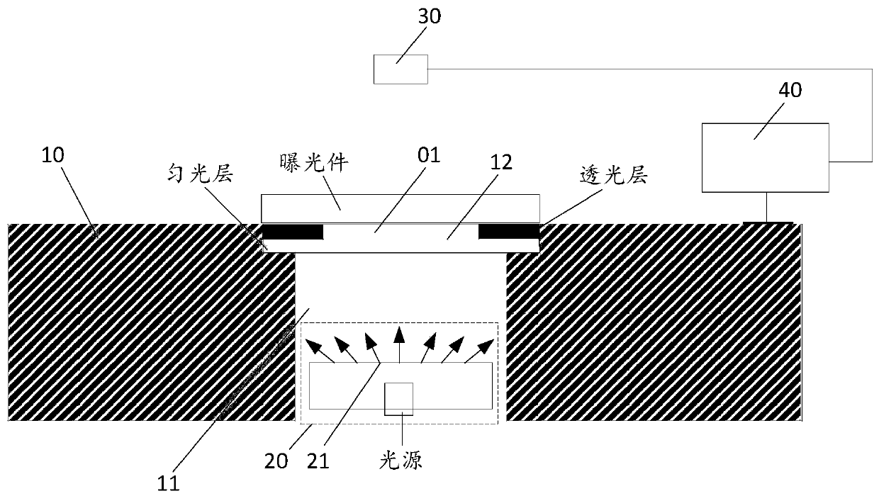
[0034] An embodiment of the present invention provides a laser direct imaging device, such as image 3As shown, the equipment includes: a workbench 10, a through hole 11 is arranged on the table surface of the workbench 10, and a light shielding sheet 12 with a light-transmitting hole 01 is arranged in the through hole 11; a laser device 20 is arranged on the...


PUM


Abstract

The invention relates to the technical field of exposure, in particular to a laser direct imaging device which comprises a workbench, a laser device, an image acquisition device and computer equipment. The table top of the workbench is provided with a through hole, and an anti-dazzling screen with a light transmitting hole is arranged in the through hole; the laser device is arranged under the table top of the workbench, a light outlet of the laser device is aligned with the through hole and used for emitting light to an exposure part through the through hole to form an alignment mark, the area of a light outlet light spot of the laser device is larger than the cross section area of the light transmitting hole, and the size of the alignment mark is consistent with that of the light transmitting hole; the image acquisition device is arranged over the workbench and is used for acquiring an alignment mark on the exposure part; and the computer equipment is connected with the image acquisition device and is used for calculating an alignment error of the exposure part according to the alignment mark acquired by the image acquisition device. The equipment solves the problem of incompleteexposure pattern caused by misalignment of the sleeve and the center of the through hole of the traditional laser imaging equipment, so that the double-sided exposure alignment of the exposure part is more accurate.

Description

technical field [0001] The invention relates to the field of exposure technology, in particular to a laser direct imaging device. Background technique [0002] Printed circuit boards (PCB for short) are one of the important components of the electronics industry, and are widely used in various electronic devices due to their small area, easy integration, and high density. PCB boards are generally divided into single-sided boards and double-sided boards. Single-sided boards usually use screen printing or optical imaging to make circuit graphics on the surface of PCB boards. Double-sided boards have two layers of positive and negative circuit graphics. The circuit graphics on the reverse side are conducted. If the circuit graphics on the front and back sides are offset, there will be misconduct or non-conduction phenomenon, which will directly cause the double panel to be scrapped. Therefore, the alignment of the graphics on the front and back sides of the double panel is PCB ...

Claims


Application Information

Patent Timeline
Patent Type & Authority Applications(China)
IPC IPC(8): G03F9/00
CPCG03F9/7046G03F9/7073
Inventor 龚双平陈国军马迪吴景舟
Owner GIS TECH INC
Why Eureka
Try Eureka