Flue gas denitration control method with future NOX emission prediction function

A control method and emission technology, applied in the direction of adaptive control, general control system, control/regulation system, etc., can solve the problems of PID control lag, large disturbance, large delay, etc., and achieve the effect of solving hysteresis overshoot

Inactive Publication Date: 2020-08-07
SHANDONG JIAOTONG UNIV
View PDF6 Cites 3 Cited by
  • Summary
  • Abstract
  • Description
  • Claims
  • Application Information

AI Technical Summary

Problems solved by technology

However, since NH 3 The reaction with NOx is a process with a large delay and large inertia. In addition, the filtration-continuous sampling-condensation-secondary filtration-chemical analysis process of the NOx online monitoring instrument CEMS also has a significant delay. In such a large-delay system , after the ammonia injection flow adjustment gate is changed, it always takes a long delay time to affect the NO X The monitoring quantity changes, so the traditional PID control always has obvious hysteresis overshoot or even divergence characteristics; not only that, the change of boiler exhaust NOx content is a very complicated process, which is affected by unit load, air volume, coal volume, Parameters such as the type of coal and the opening of the SOFA damper at the top of the low-nitrogen burner have a great influence, and they all have different delay characteristics; The strong disturbance characteristics of flue gas NOx changes lead to huge disturbances from inside and outside the system. Traditional manual control, PID automatic control and other on-site control methods are difficult to solve such industrial control problems

Method used


Image

  • Flue gas denitration control method with future NOX emission prediction function
  • Flue gas denitration control method with future NOX emission prediction function
  • Flue gas denitration control method with future NOX emission prediction function

Examples


Embodiment Construction

[0029] The present invention will be further described below in conjunction with the drawings and embodiments.

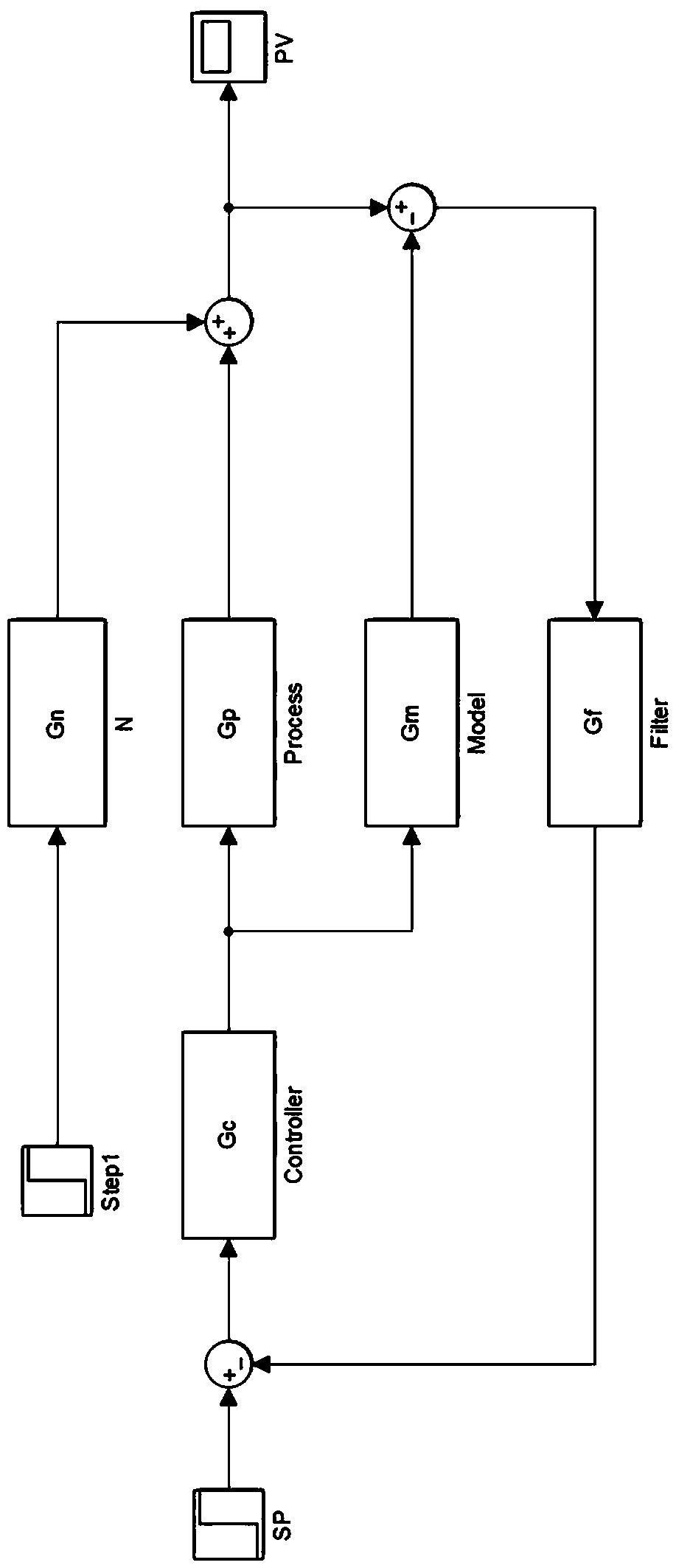
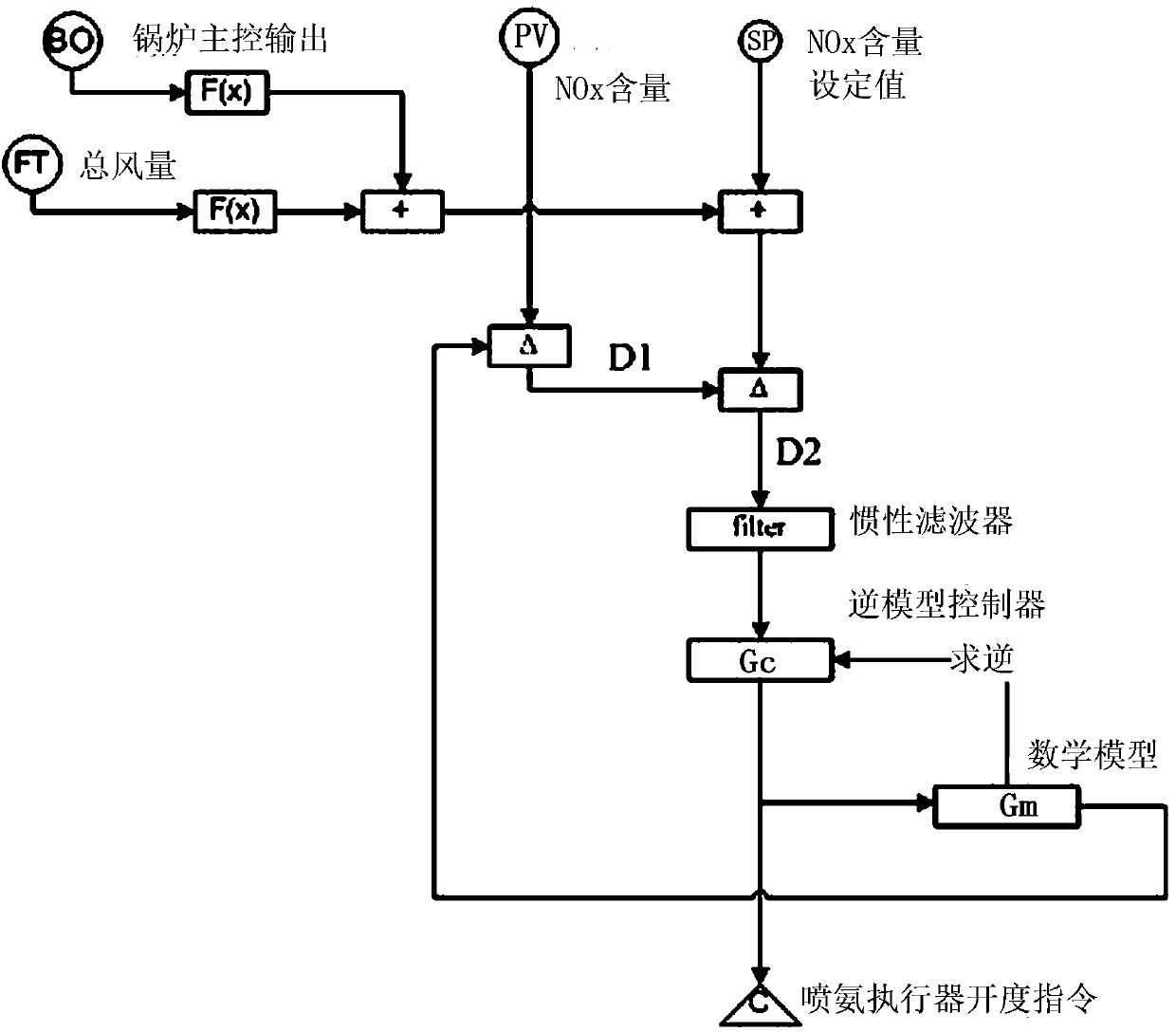
[0030] Such as figure 1 with figure 2 As shown, the control principle diagram and the SAMA engineering configuration diagram of the flue gas denitration control method with the future NOx emission prediction function of the present invention are respectively given, figure 1 Where SP is the set value of NOx emissions, G c Is the model controller, G m Is a mathematical model, G p To control the industrial process of NOx emissions, G n In order to cause the disturbance of NOx emissions, STEP1 is the disturbance source; PV is the industrial process G p And the disturbance process G n The superimposed amount of, which is detected by a sensor or transmitter. figure 2 Among them, BO is the boiler main control output, FT is the total air volume, F(X) is the function, + is the addition, Δ is the deviation (difference), FILTER is the inertial filter, and C is the ammonia inject...


PUM


Abstract

The invention discloses a flue gas denitration control method with a future NOx emission prediction function. The flue gas denitration control method comprises the following steps: a) solving an opening instruction C of an ammonia spraying actuator; b) acquiring an actual value of the NOx emission; c) solving a predicted value of the NOx emission amount; d) solving a correction value of the SP; and e) inputting a control mode. The invention discloses a flue gas denitration control method. The model controller calculates and processes the NOx emission actual value PV, the set value SP, the NOxemission predicted value, the boiler main control output and the total air volume to generate an ammonia spraying actuator opening instruction C; the change of the NOx emission amount can be pre-judged; therefore, before the change of NOx is collected by the automatic flue gas monitoring system CEMS, the output instruction of the actuator is accurately corrected and controlled in advance, the problem that obvious hysteretic overshoot and even divergence characteristics always occur in existing PID control is solved, and stable and accurate NOx emission can still be continuously obtained on a production site with strong disturbance.

Description

Technical field [0001] The invention relates to a flue gas denitration control method, and more specifically, to a flue gas denitration control method with a future NOx emission prediction function. Background technique [0002] Nitrogen oxide (NOx) emission control has been listed as the focus of emission reduction in my country at this stage. In this context, newly installed thermal power generating units will be equipped with denitrification devices, and old units that have been built and put into production have also been retrofitted with SCR or SNCR denitrification systems. Selective catalytic reduction method SCR process is a mature industrial denitrification technology. Its principle is to selectively reduce NO and NOx to N under the action of a catalyst at a flue gas temperature of 300-400℃ 2 , And almost no NH 3 And O 2 的oxidation reaction. Theoretically, by reasonably controlling the temperature of the reaction zone and the amount of ammonia sprayed, NH 3 While the esc...

Claims


Application Information

Patent Timeline
Patent Type & Authority Applications(China)
IPC IPC(8): G05B13/04
CPCG05B13/042
Inventor 潘为刚王目树徐丽娜
Owner SHANDONG JIAOTONG UNIV
Why Eureka
Try Eureka