
Optimization method for capacity allocation of grid-side energy storage system

A technology for energy storage system and capacity allocation, applied in the direction of circuit devices, AC network circuits, AC network load balancing, etc., can solve the scientific consideration of lack of application effect, no better solution, and no consideration of the utilization efficiency of energy storage system And other issues

Active Publication Date: 2021-02-19
湖南经研电力设计有限公司 +1
View PDF0 Cites 0 Cited by
  • Summary
  • Abstract
  • Description
  • Claims
  • Application Information

AI Technical Summary

Problems solved by technology

However, most of the grid-side energy storage projects that have been implemented adopt the "top-down" mode in capacity planning, mainly based on the total amount and site conditions for empirical configuration, and lack of scientific consideration for the best application effect
[0005] In addition, the current energy storage system configuration research is mostly aimed at new energy and user-side applications. In terms of grid-side energy storage configuration, more consideration is given to the overall application effect of the energy storage system, such as grid reliability and economic benefits. For energy storage System utilization efficiency is not considered
This makes the current energy storage system capacity configuration process on the grid side, there is no better solution

Method used


Image

  • Optimization method for capacity allocation of grid-side energy storage system
  • Optimization method for capacity allocation of grid-side energy storage system
  • Optimization method for capacity allocation of grid-side energy storage system

Examples


Embodiment Construction

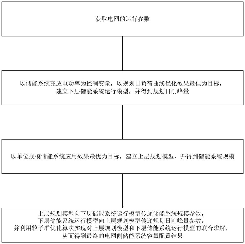
[0052] Such as figure 1 Shown is a schematic flow chart of the method of the present invention: the method for optimizing the capacity configuration of the grid-side energy storage system provided by the present invention includes the following steps:

[0053] S1. Obtain the operating parameters of the power grid;

[0054] S2. Taking the charging and discharging power of the energy storage system as the control variable, aiming at the best optimization effect of the planned daily load curve, establish the operation model of the lower energy storage system, and obtain the planned daily peak shaving amount; specifically, the following steps are used to establish the lower energy storage The system runs the model and calculates the planned daily peak shaving amount:

[0055] A. Use the following formula as the objective function of the underlying energy storage system operation model:

[0056]

[0057] where S ess is the battery capacity of the energy storage system; P ess...


PUM


Abstract

The invention discloses a capacity configuration optimization method for a power grid side energy storage system. The method comprises the steps of obtaining operation parameters of a power grid; establishing a lower-layer energy storage system operation model and obtaining a planned daily peak clipping amount; establishing an upper-layer planning model and obtaining the scale of the energy storage system; and jointly solving the upper-layer planning model and the lower-layer energy storage system operation model by using a particle swarm optimization algorithm to obtain a final capacity configuration result of the power grid side energy storage system. According to the method, a unit-scale application effect model of the power grid side energy storage system is established, a method for calculating the application effect of the power grid side energy storage system on a multi-voltage-level power grid and a power supply is provided, and the advantage that one part of energy storage isapplied and multiple parts are benefited is fully reflected; an upper-layer and lower-layer optimal configuration model of the power grid side energy storage system is established, and an improved particle swarm algorithm is adopted to perform optimal calculation, so that a comprehensive optimal configuration result can be obtained quickly; therefore, the method is high in reliability and good inpracticability, and gives consideration to the overall effect and utilization efficiency of the power grid side energy storage system.

Description

technical field [0001] The invention belongs to the field of electrical automation, and in particular relates to a method for optimizing capacity configuration of an energy storage system on a grid side. Background technique [0002] With the development of economy and technology and the improvement of people's living standards, electric energy has become an indispensable secondary energy source in people's production and life, bringing endless convenience to people's production and life. Therefore, the stable and reliable operation of the power system has become one of the most important tasks of the power system. [0003] In the power industry, wind energy, solar energy and other new energy and smart grid industries are rapidly rising. However, due to the unstable output of new energy sources, the safe and stable operation of the power grid is facing challenges. Energy storage technology is considered to be an important solution to the problem of high proportion of new e...

Claims


Application Information

Patent Timeline
Patent Type & Authority Patents(China)
IPC IPC(8): H02J3/32
CPCH02J3/32H02J2203/20
Inventor 吴昌龙罗华伟徐志强禹海峰陈霖华欧名勇
Owner 湖南经研电力设计有限公司
Learn More