
Pipeline protecting device based on temporary beam

A pipeline protection and convenient beam technology, which is applied in the field of pipeline protection devices based on convenient beams, can solve the problems of no pipeline, fracture, existing pipeline damage, etc., and achieve the effects of reducing labor intensity, occupying less space, and saving installation time.

Active Publication Date: 2020-08-11
中铁二十四局集团江苏工程有限公司
View PDF7 Cites 1 Cited by
  • Summary
  • Abstract
  • Description
  • Claims
  • Application Information

AI Technical Summary

Problems solved by technology

[0002] During the construction of railway business lines, a large number of equipment and pipelines are often involved. Usually, the existing pipelines are simply cut and connected and then directly pass through the construction site, so that the pipelines are directly stacked on the ground. The situation is complicated, and the use of large-scale machinery is ordinary, which can easily cause damage or even break the existing pipeline. At present, there is no device for pipeline protection in the construction process.

Method used


Image

  • Pipeline protecting device based on temporary beam
  • Pipeline protecting device based on temporary beam
  • Pipeline protecting device based on temporary beam

Examples


Embodiment

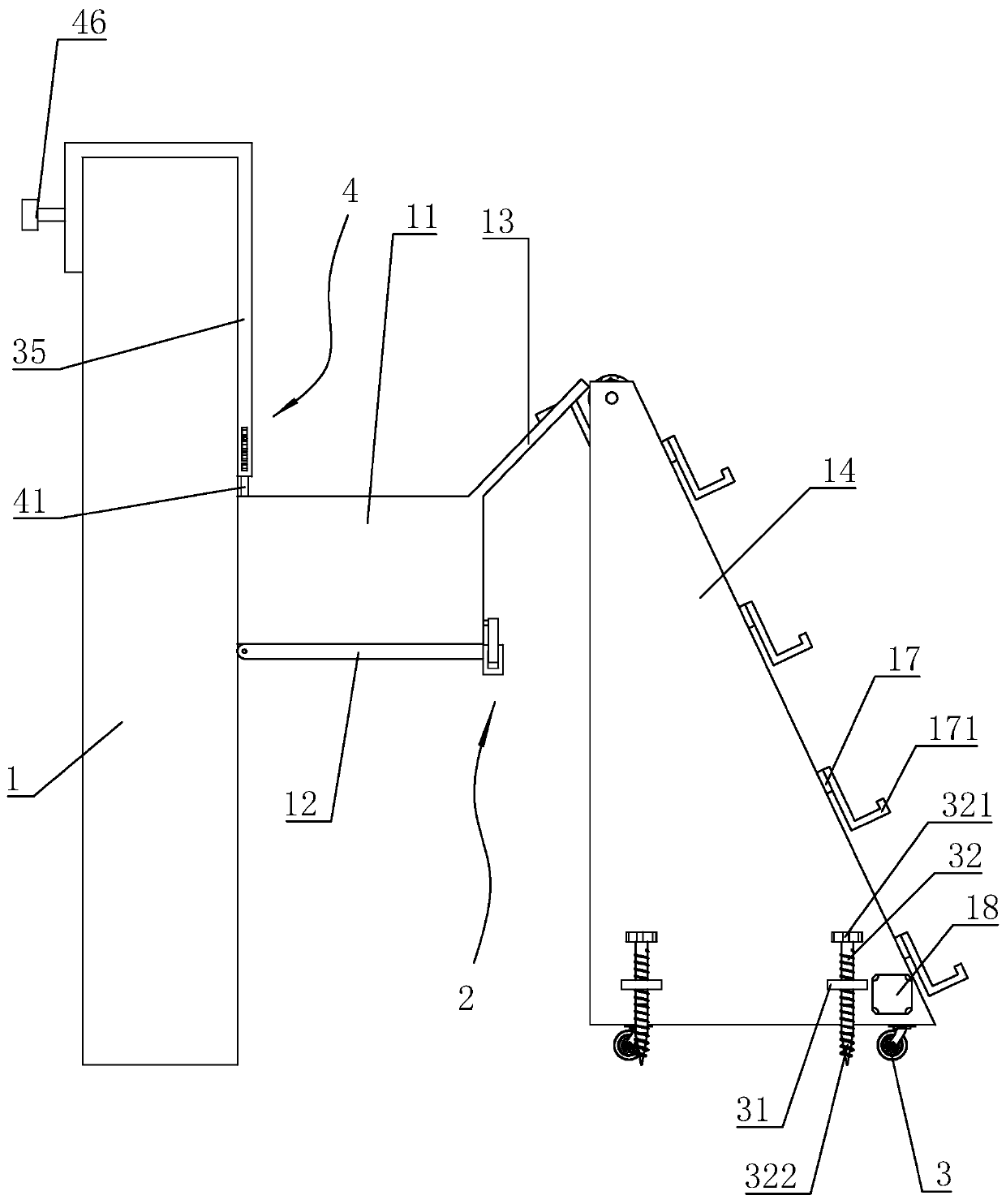
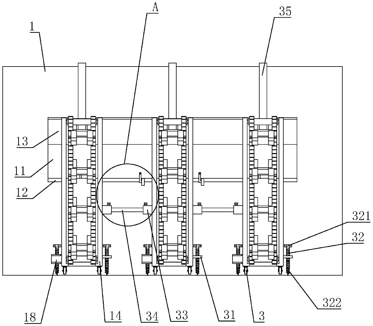
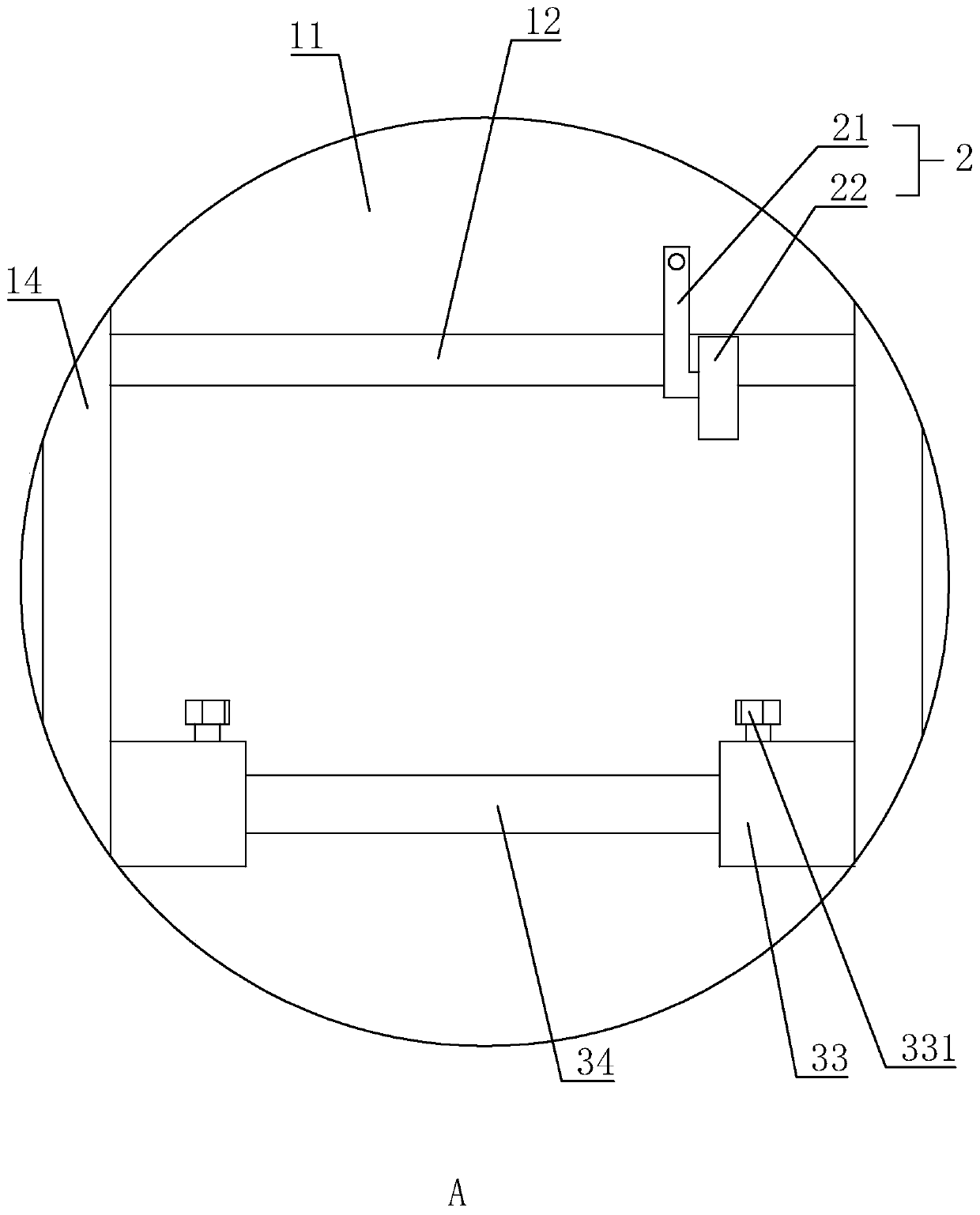
[0036] Embodiment: a kind of pipeline protection device based on convenient beam, such as figure 1 and Figure 4 As shown, it includes a beam 1, a material frame 11 and a support frame 14. The material frame 11 is connected to the side wall of the beam 1 and extends along the length of the beam 1. The material frame 11 is higher than the ground, and the bottom of the material frame 11 is hinged. For the end cover 12 that closes the lower frame opening, the end cover 12 is provided with a buffer pad 23, and the material frame 11 is provided with a limiting member 2 for restricting the rotation of the end cover 12; And the hooks 21 equidistantly distributed along its length direction, the side wall of the end cover 12 is provided with the buckle 22 corresponding to the hook 21 one by one, the operator can hang the end cover by rotating the hook 21 and the buckle 22 12. Fix the end cap 12.

[0037] Such as Figure 4 As shown, the side of the material frame 11 away from the bea...


PUM


Abstract

The invention relates to a pipeline protecting device based on a temporary beam. The pipeline protecting device is applied to the technical field of railway construction. The key point of the technical scheme is as follows: the pipeline protecting device comprises the temporary beam. A material frame extending in a length direction of the temporary beam is connected to the side wall of the temporary beam, an end cover for closing a lower frame port is hinged to the bottom of the material frame, and a limiting part for limiting rotation of the end cover is arranged on the material frame. A material guide plate extending upward obliquely is arranged at the upper frame port of the side, far away from the temporary beam, of the material frame, a plurality of supporting racks distributed in a spaced manner in the length direction of the material frame are arranged on the ground, two ends of each supporting rack in a height direction are rotatably connected to center shafts, the two center shafts are provided with a plurality of symmetrically distributed synchronizing wheels, and opposite two synchronizing wheels are connected by a synchronizing belt. The pipeline protecting device has the advantages that pipelines are stored in a protecting box, so that a condition that the pipelines are damaged in actual construction is reduced, and meanwhile, the protecting box which takes the temporary beam as a carrier combines the temporary beam with pipeline protection, so that the pipeline protecting device is convenient and flexible.

Description

technical field [0001] The invention relates to the technical field of railway construction, in particular to a pipeline protection device based on a side beam. Background technique [0002] During the construction of railway business lines, a large number of equipment and pipelines are often involved. Usually, the existing pipelines are simply cut and connected and then directly pass through the construction site, so that the pipelines are directly stacked on the ground. The situation is complicated, and the use of large-scale machinery is ordinary, which can easily cause damage or even break the existing pipeline. At present, there is no device for pipeline protection during the construction process. D-shaped beams are often used in the actual construction of business lines. D-shaped beams have good bearing capacity. Therefore, how to combine D-shaped beams with pipeline protection devices has become an urgent problem in this industry. Contents of the invention [0003]...

Claims


Application Information

Patent Timeline
Patent Type & Authority Applications(China)
IPC IPC(8): B65G17/12B65G17/32B65G41/00B65G47/34E04G21/30H02G9/02
CPCB65G17/12B65G17/32B65G41/008B65G47/34E04G21/30H02G9/025
Inventor 王飞球王家俊汪宗冬孙剑健
Owner 中铁二十四局集团江苏工程有限公司
Learn More