Cabinet-type transformer substation
A substation and cabinet-type technology, applied in the field of power equipment, can solve problems such as poor cooling effect
- Summary
- Abstract
- Description
- Claims
- Application Information
AI Technical Summary
Problems solved by technology
Method used
Image

Examples
Embodiment Construction
[0029] Specific embodiments of the present invention will be described in detail below in conjunction with the accompanying drawings. It should be understood that the specific embodiments described here are only used to illustrate and explain the present invention, and are not intended to limit the present invention.
[0030] In the present invention, unless otherwise specified, the orientation words included in the term such as "up, down, left, right, front, back, inside and outside" only represent the orientation of the term in the normal use state, or the common name understood by those skilled in the art. , and should not be construed as a limitation of this term.
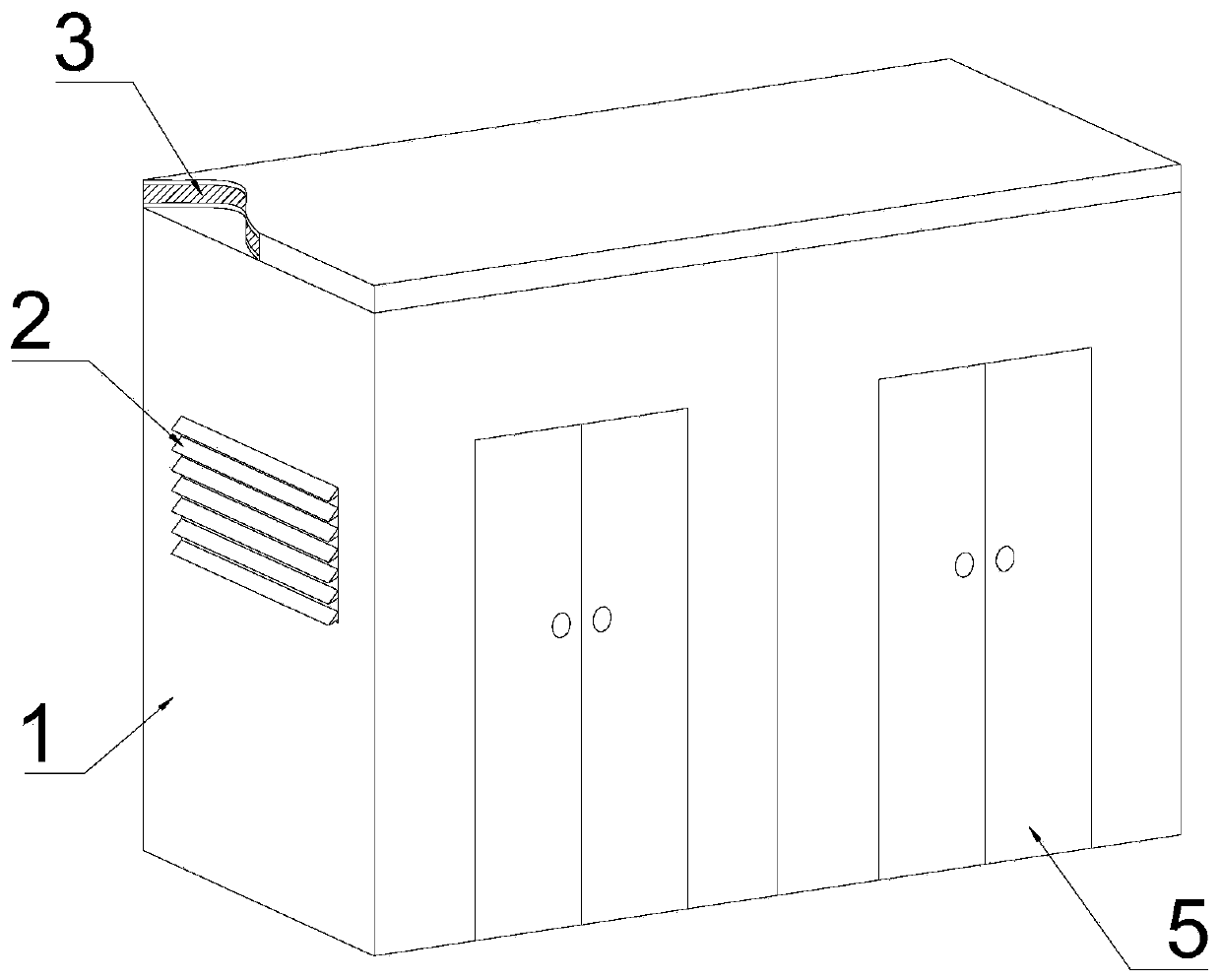
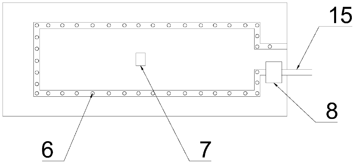
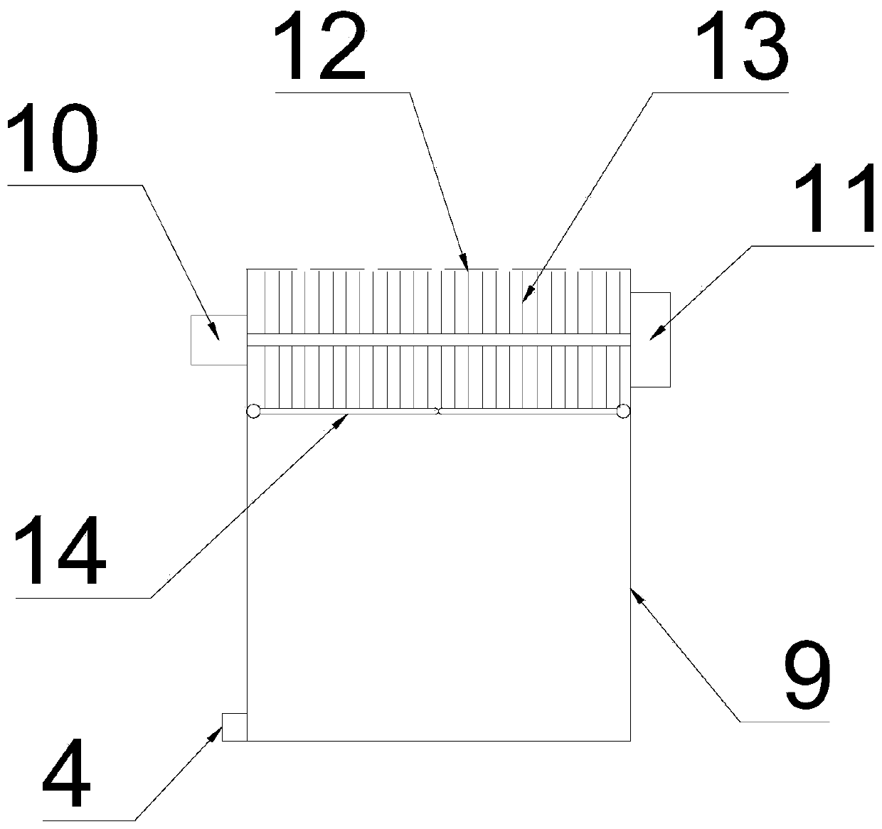
[0031] see Figure 1-3 The cabinet-type substation shown includes: a station body 1, at least one door body 5 is arranged on the front side of the station body 1, and the left and / or right sides of the station body 1 are arranged There are shutters 2; the inner top of the station body 1 is provided with a spr...
PUM
 Abstract
Description
Claims
Application Information
PatSnap Eureka turns technology decisions into work you can execute. Powered by our Innovation Knowledge Graph, it runs expert workflows across engineering, life sciences, materials and intellectual property. Get your review-ready output in minutes.


