Tubular workpiece fluid abrasive finishing device and finishing method thereof

A technology of finishing and fluid abrasives, applied in the direction of grinding drive device, grinding workpiece support, metal processing equipment, etc., can solve problems such as fixture sealing problem, eliminate processing error, shorten processing time, and achieve obvious processing effect. Effect

Active Publication Date: 2020-08-14
TAIYUAN UNIV OF TECH
View PDF8 Cites 5 Cited by
  • Summary
  • Abstract
  • Description
  • Claims
  • Application Information

AI Technical Summary

Problems solved by technology

[0005] In order to overcome the deficiencies of the prior art, solve how to ensure that the abrasive does not enter the gap between the workpiece and the fixture, and process multiple workpieces in groups to solve the problem of the sealing of the fixture, the present invention provides a fluid abrasive light for tubular workpieces. Finishing device and finishing method thereof

Method used


Image

  • Tubular workpiece fluid abrasive finishing device and finishing method thereof
  • Tubular workpiece fluid abrasive finishing device and finishing method thereof
  • Tubular workpiece fluid abrasive finishing device and finishing method thereof

Examples


Embodiment 1

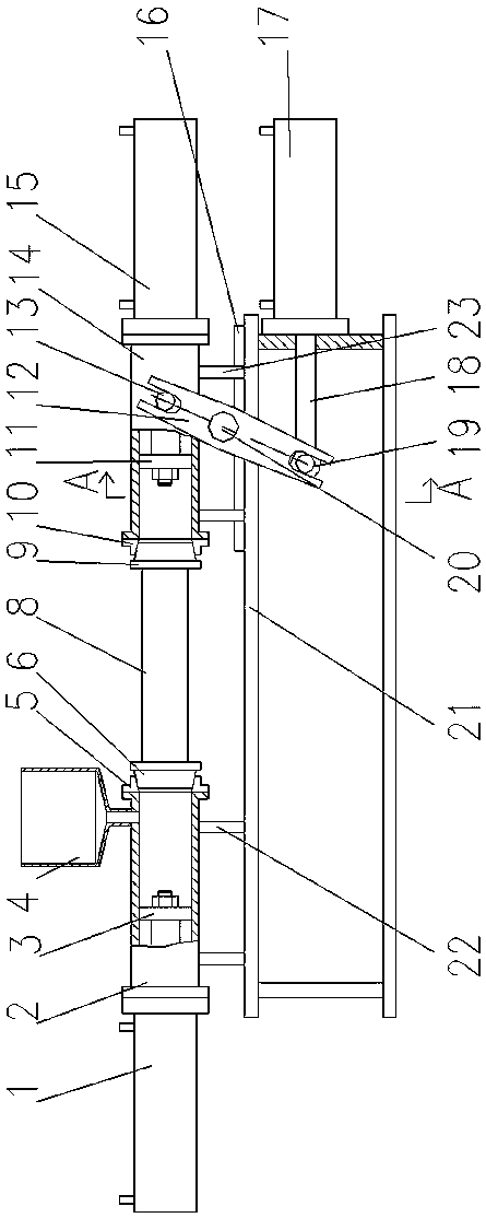
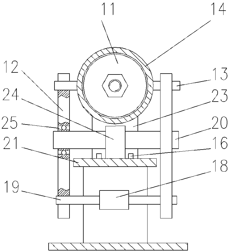
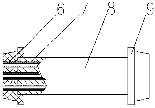
[0036] like Figure 1 to Figure 4 A fluid abrasive finishing device for tubular workpieces is shown, which includes a frame 21, a hydraulic cylinder, a pusher cylinder and a tubular workpiece fixture 8, and the hydraulic cylinder includes a left hydraulic cylinder 1, a right hydraulic cylinder 15 and a lower hydraulic cylinder 17. The pushing cylinder includes a left pushing cylinder 2 and a right pushing cylinder 14, wherein:

[0037] The right side of the upper surface of the frame 21 is provided with a guide rail 16, the left support frame 22 is arranged on the top of the left side of the frame 21, the right support frame 23 is arranged on the top of the guide rail 16, and the right support frame 23 reciprocates horizontally along the guide rail 16 sports;

[0038] The left push cylinder 2 is fixedly installed on the left support frame 22 along the horizontal direction, the left hydraulic cylinder 1 is arranged on the left side of the left push cylinder 2, and the piston rod...

Embodiment 2

[0056] The finishing method of a fluid abrasive finishing device for tubular workpieces provided in the second embodiment is the same as that described in the first embodiment, and will not be repeated here.

[0057] The fluid abrasive finishing device for tubular workpieces provided in the second embodiment is different in that the tubular workpiece clamp 8 between the two rubber pads is replaced with a non-straight circular tube clamp on the basis of the first embodiment. For example, curved pipe workpiece fixtures can also achieve the effect of finishing the inner wall of the pipe.


PUM


Abstract

The invention relates to a tubular workpiece fluid abrasive finishing device and a finishing method thereof, belongs to the technical field of part inner surface polishing, and solves the technical problem that abrasive enters a gap between a workpiece and a clamp. The device comprises a rack, a hydraulic cylinder, a pushing cylinder and a tubular workpiece clamp, and a guide rail is arranged on the right side of the upper surface of the rack; a left supporting frame is arranged above the left side of the rack, a right supporting frame horizontally reciprocates along the guide rail, and a lower hydraulic cylinder is fixedly installed on the rack below the right supporting frame in the horizontal direction; and a tubular workpiece is clamped in an inner cavity of the tubular workpiece clamp, rubber pads are oppositely arranged at the left end and the right end of the tubular workpiece clamp, the left end of the left rubber pad is installed in a left material extruding pipe, the left endof the right rubber pad is installed in a right material extruding pipe, the left end of the tubular workpiece is installed in the left rubber pad, and the right end of the tubular workpiece is installed in the right rubber pad. According to the device, all grinding materials can enter a to-be-machined tubular workpiece, the machining effect is obvious, and the end face effect cannot be generatedat the two ends of the tubular workpiece.

Description

technical field [0001] The invention belongs to the technical field of inner surface polishing of parts, and in particular relates to a fluid abrasive finishing device and a finishing method for pipe workpieces. Background technique [0002] With the development of the manufacturing industry and the diversification of social needs, the demand for high-quality smooth surfaces of products is becoming more and more extensive, and the requirements for the effect of finishing parts are getting higher and higher. A large number of round tube parts, such as aero-engine fuel pipes and other thin round tube parts, have high finishing requirements for low-roughness and smooth surfaces in specific applications, especially the roughness value is required to be reduced to Ra0. 1 or less. Although electrolytic and chemical polishing methods can achieve lower surface roughness, serious environmental pollution and other problems make it difficult to use on a large scale. Therefore, it is u...

Claims


Application Information

Patent Timeline
Patent Type & Authority Applications(China)
IPC IPC(8): B24B31/10B24B31/12B24B31/14B24B41/06B24B47/22
CPCB24B31/10B24B31/12B24B31/14B24B41/06B24B47/22
Inventor 董志国马志鹏张宇超雷鸿博
Owner TAIYUAN UNIV OF TECH
Why Eureka
Try Eureka