Grid-connected inverter and dead zone phase shift compensation method thereof

A technology of phase shift compensation and inverter, which is applied in the direction of AC network circuit, single network parallel feeding arrangement, AC power input conversion to DC power output, etc. It can solve grid-connected current distortion, no compensation method, and maximum voltage Problems such as the decrease of utilization rate can achieve the effect of precise control of grid-connected current phase and adjustment of active and reactive power, which is conducive to accurate phase control and improves the accuracy of grid-connected control.

Active Publication Date: 2020-08-14
SHANGHAI JIAO TONG UNIV
View PDF6 Cites 0 Cited by
  • Summary
  • Abstract
  • Description
  • Claims
  • Application Information

AI Technical Summary

Problems solved by technology

[0003] The addition of dead time will cause some problems that deviate from the ideal modulation. So far, the main concerns of people are: (1) Under the same modulation degree, the effective value of the fundamental wave of the output phase voltage (or line voltage) drops, that is, the maximum voltage Utilization rate decreases; (2) The output phase voltage (line voltage) is distorted according to the average value of the switching cycle, that is, the actual output fundamental phase voltage (or line voltage) is distorted, causing distortion and phase shift of the grid-connected current ;
But up to the present, also do not appear above-mentioned corresponding compensation method, also do not find explanation or report with similar technology of the present invention, and similar data both at home and abroad

Method used


Image

  • Grid-connected inverter and dead zone phase shift compensation method thereof
  • Grid-connected inverter and dead zone phase shift compensation method thereof
  • Grid-connected inverter and dead zone phase shift compensation method thereof

Examples


Embodiment Construction

[0063] The present invention will be described in detail below in conjunction with specific embodiments. The following examples will help those skilled in the art to further understand the present invention, but do not limit the present invention in any form. It should be noted that those skilled in the art can make several changes and improvements without departing from the concept of the present invention. These all belong to the protection scope of the present invention.

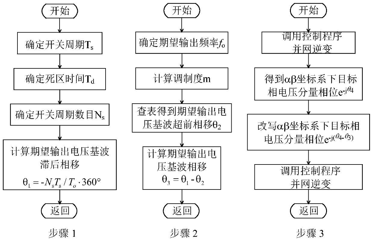
[0064] The grid-connected inverter dead zone phase shift compensation method provided by the embodiment of the present invention is a grid-connected inverter PWM modulation algorithm dead zone injection causes the fundamental wave of the output voltage to lead the phase shift, and the modulation algorithm switching cycle beat causes the output Compensation method for lagging phase shift of voltage fundamental wave.

[0065] Such as figure 1 As shown, the grid-connected inverter dead zone phase shift co...


PUM


Abstract

The invention provides a grid-connected inverter and a dead zone phase shift compensation method thereof. The dead zone phase shift compensation method comprises the steps of calculation of phase shaft cased by lagging by determining a switching period of the grid-connected inverter, determining dead time of the grid-connected inverter, determining the number of delay switching periods required for generating a PWM driving signal of the grid-connected inverter, and calculating the lagging phase shift caused by switching period beat; calculation of phase shift caused by dead zone by determiningthe expected output voltage frequency of the grid-connected inverter, determining the modulation degree of the grid-connected inverter, obtaining expected output voltage fundamental wave leading phase shift caused by a dead zone and calculating an expected output voltage fundamental wave total phase shift; and fundamental wave phase shift compensation by obtaining a target phase voltage componentphase under an alpha beta coordinate system, rewriting a target phase voltage component phase under an alpha-beta coordinate system, and calling an SVPWM or SPWM program in the grid-connected inverter control program to generate a grid-connected inverter driving signal for grid connection. The method is beneficial to accurate phase control of the grid-connected inverter and has the advantages ofbeing simple, clear in logic, capable of improving grid-connected control precision and the like.

Description

technical field [0001] The invention relates to the technical field of grid-connected inverters, in particular to a grid-connected inverter and a dead zone phase shift compensation method thereof, which are used for high-precision phase grid-connected grid-connected inverters. Background technique [0002] Grid-connected inverters are widely used in photovoltaic power generation, wind power generation and other application fields. As a grid-connected inverter (VSI) powered by DC voltage, when the working state of the upper and lower power switches of the same bridge arm is switched, it is necessary to set a sufficiently long dead Zone time, in order to prevent the bridge arm direct current short circuit caused by the power switch overcurrent damage. [0003] The addition of dead time will cause some problems that deviate from the ideal modulation. So far, the main concerns of people are: (1) Under the same modulation degree, the effective value of the fundamental wave of the...

Claims


Application Information

Patent Timeline
Patent Type & Authority Applications(China)
IPC IPC(8): H02M1/38H02M7/5395H02J3/38
CPCH02J3/38H02M1/38H02M7/5395H02J2203/20H02M1/385
Inventor 侯孝涵常中科陈熠杨喜军
Owner SHANGHAI JIAO TONG UNIV
Why Eureka
Try Eureka