
A variable frequency speed-regulating inverter and a method for compensating for phase shift caused by dead zone

A technology of phase shift compensation and frequency conversion speed regulation, which is applied in the direction of controlling electromechanical brakes, converting AC power input to DC power output, motor generator control, etc., and can solve the problems of no explanation or report, torque ripple, and no compensation method and other problems, to achieve the effect of accurate measurement, improvement of measurement accuracy, and perfect phase control

Active Publication Date: 2021-06-29
SHANGHAI JIAOTONG UNIV
View PDF8 Cites 0 Cited by
  • Summary
  • Abstract
  • Description
  • Claims
  • Application Information

AI Technical Summary

Problems solved by technology

[0003] The addition of dead time will cause some problems that deviate from the ideal modulation. So far, the main concerns of people are: (1) Under the same modulation degree, the effective value of the fundamental wave of the output phase voltage (or line voltage) drops, that is, the maximum voltage The utilization rate decreases; (2) The output phase voltage (line voltage) is distorted according to the average value of the switching cycle, that is, the actual output fundamental phase voltage (or line voltage) is distorted, causing motor current distortion and torque ripple;
But up to the present, also do not appear above-mentioned corresponding compensation method, also do not find explanation or report with similar technology of the present invention, and similar data both at home and abroad

Method used


Image

  • A variable frequency speed-regulating inverter and a method for compensating for phase shift caused by dead zone
  • A variable frequency speed-regulating inverter and a method for compensating for phase shift caused by dead zone
  • A variable frequency speed-regulating inverter and a method for compensating for phase shift caused by dead zone

Examples


Embodiment Construction

[0066] The present invention will be described in detail below in conjunction with specific embodiments. The following examples will help those skilled in the art to further understand the present invention, but do not limit the present invention in any form. It should be noted that those skilled in the art can make several changes and improvements without departing from the concept of the present invention. These all belong to the protection scope of the present invention.

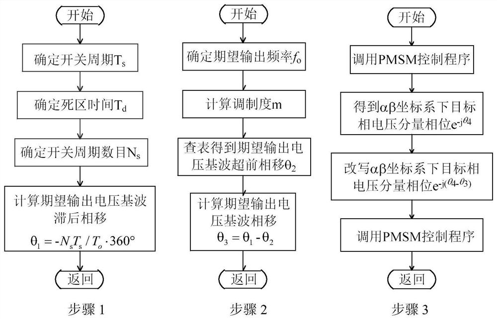
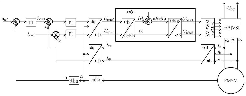
[0067] The embodiment of the present invention provides a phase shift compensation method caused by the dead zone of the variable frequency speed control inverter, which is a PWM modulation algorithm dead zone injection of the variable frequency speed control inverter causes the fundamental wave of the output voltage to lead the phase shift and modulate the switch cycle difference The compensation method for the lagging phase shift of the fundamental wave of the output voltage caused by beats.

[0068] ...


PUM


Abstract

The present invention provides a frequency conversion speed regulation inverter and its phase shift compensation method caused by the dead zone, including: phase shift calculation caused by the beat: determining the switching period of the inverter; determining the dead zone time of the inverter; determining the delay switching period Calculate the lag phase shift caused by the switching cycle beat; the phase shift caused by the dead zone Calculation process: determine the expected output voltage frequency of the inverter; determine the modulation degree; obtain the leading phase shift of the expected output voltage fundamental wave caused by the dead zone; calculate the expected The total phase shift of the fundamental wave of the output voltage; the fundamental phase shift compensation process: obtain the phase of the target phase voltage component in the αβ coordinate system; rewrite the phase of the target phase voltage component in the αβ coordinate system; call the SVPWM or SPWM program in the permanent magnet synchronous motor control program An inverter drive signal is generated to control a permanent magnet synchronous motor. The invention realizes perfect phase control, is beneficial to the precise measurement of the rotor position of the PMSM, has the advantages of simplified method and clear logic, and can improve the control precision of the PMSM.

Description

technical field [0001] The invention relates to the technical field of frequency conversion and speed regulation, in particular to a frequency conversion and speed regulation inverter and a phase shift compensation method caused by a dead zone thereof, which are used for precise power supply of frequency converters. Background technique [0002] The post-stage circuit of the frequency conversion speed control inverter is a voltage source inverter, which is widely used in industrial frequency conversion speed control, frequency conversion household appliances and other applications, including permanent magnet synchronous motor (PMSM) vector control system, as a DC voltage power supply For a voltage source inverter (VSI), when the working state of the upper and lower power switches of the same bridge arm is switched, it is necessary to set a long enough dead time to prevent the bridge arm from passing through and causing a short circuit of the DC power supply and causing the po...

Claims


Application Information

Patent Timeline
Patent Type & Authority Patents(China)
IPC IPC(8): H02M1/38H02M7/5395H02P27/08H02P21/14H02P25/026
CPCH02M1/38H02M7/5395H02P21/14H02P25/026H02P27/085H02P2207/05H02M1/385
Inventor 侯孝涵常中科陈熠杨喜军
Owner SHANGHAI JIAOTONG UNIV
Learn More