
Outdoor constant-temperature bench

A bench and constant temperature technology, applied to chairs, stools, other seating furniture, etc., can solve the problems of low surface temperature and high surface temperature, achieve temperature balance, improve comfort, and delight the mood

Pending Publication Date: 2020-08-18
孙健
View PDF0 Cites 0 Cited by
  • Summary
  • Abstract
  • Description
  • Claims
  • Application Information

AI Technical Summary

Problems solved by technology

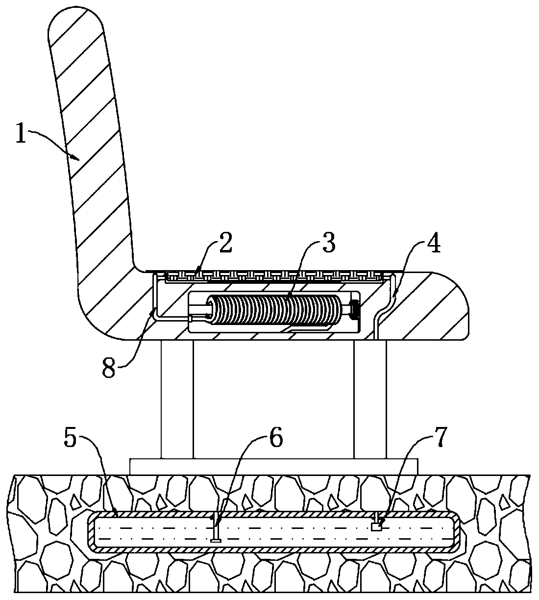
[0003] The purpose of the present invention is to solve the shortcomings of the outdoor benches in the prior art that the surface temperature is high in summer and the surface temperature is too low in winter, and proposes an outdoor constant temperature bench

Method used


Image

  • Outdoor constant-temperature bench
  • Outdoor constant-temperature bench
  • Outdoor constant-temperature bench

Examples


Embodiment 1

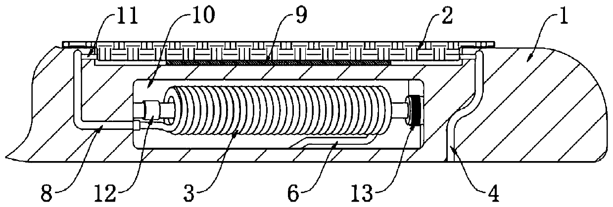
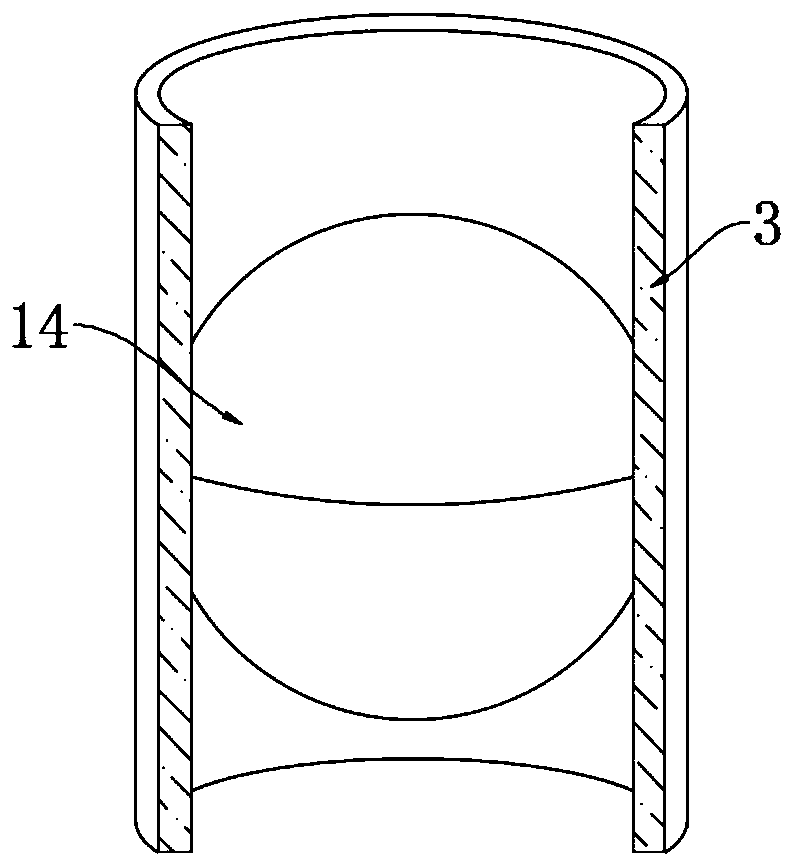
[0025] refer to Figure 1-3 , an outdoor constant temperature bench, comprising a bench body 1, a heat conduction box 5 is embedded in the ground below the bench body 1, the buried depth of the heat conduction box 5 is greater than 2m, the heat conduction box 5 is made of metal with good thermal conductivity, and the heat conduction The box 5 has been treated with anti-corrosion treatment. The bench body 1 includes a chair back and a seat seat. An elastic layer 2 is fixed on the seat seat. A piezoelectric ceramic 9 is arranged between the elastic layer 2 and the seat seat. A first The upper ends of the backflow groove 4 and the second backflow groove 8, the first backflow groove 4 and the second backflow groove 8 communicate with a plurality of shunt pipes 11, and the plurality of shunt pipes 11 are evenly distributed in the elastic layer 2, and the shunt pipes 11 are Made of hard plastic, it is not easy to deform, and an installation groove 10 is provided in the seat, and a c...

Embodiment 2

[0036] refer to Figure 4-5 , the present embodiment differs from Embodiment 1 in that: a chute 17 is provided in the seat seat, and the chute 17 is inclined downward, a metal plate 15 is provided for sealing and sliding in the chute 17, and a sounding device is installed on the bottom wall of the seat seat. Part 16, and the sounding part 16 communicates with the chute 17, and the end of the chute 17 communicates with the outside world (not shown in the figure).

[0037] A plurality of through holes 19 with different inner diameters are opened in the sounding part 16 , and each through hole 19 is provided with a reed 18 .

[0038] When this embodiment is used, the metal plate 15 is located at the lower end of the chute 17 under the action of gravity. When the solenoid 13 is energized, the magnetic field generated by it will attract the metal plate 15 to slide upwards, so that the outside air flows into the chute through the sounding part 16. Groove 17, when the air flow passe...


PUM


Abstract

The invention discloses an outdoor constant-temperature bench. The bench comprises a bench body, and a heat conduction box is buried in the ground below the bench body; the bench body comprises a bench back and a bench seat; an elastic layer is fixed on the bench seat; piezoelectric ceramic is arranged between the elastic layer and the bench seat; a first backflow groove and a second backflow groove are formed in the bench seat; the upper end of the first backflow groove and the upper end of the second backflow groove jointly communicate with a plurality of flow dividing pipes, the flow dividing pipes are evenly distributed in the elastic layer, a mounting groove is further formed in the bench seat, a circulating mechanism is arranged in the mounting groove, the circulating mechanism comprises a transverse rod horizontally fixed to the middle of the mounting groove, and one end of the transverse rod is sleeved with a magnetic ring. The comfort level of the bench can be improved, and the elastic layer is automatically cooled after pedestrians sit down to have a rest at high temperature in summer; in cold winter, the elastic layer is automatically heated after pedestrians sit down tohave a rest, and the sound production part can also produce music sounds which are rich in layering sense and rich in changes, so that people are pleasant.

Description

technical field [0001] The invention relates to the technical field of public facilities, in particular to an outdoor constant temperature bench. Background technique [0002] Benches for people to rest can be seen everywhere on both sides of the street, in parks, and in scenic spots. Most of the benches are made of plastic, wood or metal. When the summer is hot, the surface temperature of outdoor benches is very high after being exposed to the sun. High, when pedestrians need to sit down and rest, they will feel that the bench is very hot, increasing the feeling of heat; in winter, the temperature of outdoor benches is similar to the ambient temperature, and pedestrians will feel their legs are very cold when sitting on the bench. Therefore, we propose an outdoor constant temperature bench. Contents of the invention [0003] The purpose of the present invention is to solve the shortcomings of the outdoor benches in the prior art that the surface temperature is high in su...

Claims


Application Information

Patent Timeline
Patent Type & Authority Applications(China)
IPC IPC(8): A47C7/74A47C7/72A47C7/24A47C1/00
CPCA47C7/748A47C7/72A47C7/24A47C1/00
Inventor 孙健
Owner 孙健
Learn More