A B -pillar structure for installing the face recognition device

A technology of face recognition and face recognition, which is applied in the field of auto parts, can solve problems such as the difficulty of ensuring the B-pillar collision requirements, and achieve the effects of reducing the amount of upper intrusion, improving vehicle safety, and increasing strength

Active Publication Date: 2021-11-09
ZHEJIANG LEAPMOTOR TECH CO LTD
View PDF6 Cites 0 Cited by
  • Summary
  • Abstract
  • Description
  • Claims
  • Application Information

AI Technical Summary

Problems solved by technology

[0004] The present invention aims to overcome the problem in the prior art that it is difficult to ensure the collision requirements of the B-pillar after installing a face recognition device on the B-pillar, and provides a B-pillar structure for installing a face recognition device. The identification device makes the vehicle intelligent and at the same time meets the strength and stiffness requirements of the B-pillar, improving vehicle safety

Method used


Image

  • A B -pillar structure for installing the face recognition device
  • A B -pillar structure for installing the face recognition device
  • A B -pillar structure for installing the face recognition device

Examples


Embodiment 1

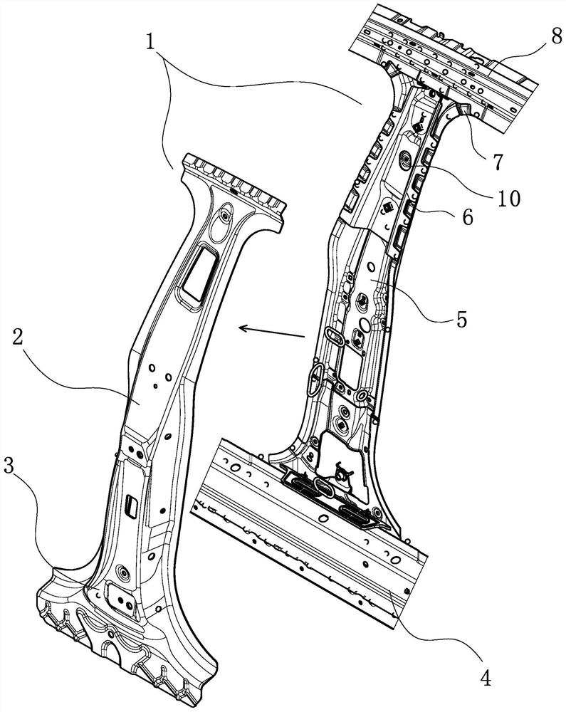
[0036] Such as figure 1 , Figure 6 In the shown embodiment 1, a B-pillar structure for installing a face recognition device includes a B-pillar body 1, and the B-pillar body 1 includes a mounting assembly, and side wall panels connected sequentially through the mounting assembly from outside to inside 2. Reinforcement panel assembly and inner panel assembly. The reinforcement panel assembly includes side beam reinforcement panel 8, B-pillar reinforcement panel 9 and face recognition reinforcement panel 6. The inner panel assembly includes side beam inner panel 7, The B-pillar inner panel 5 and the face recognition reinforcing plate 6 are fixed between the B-pillar reinforcing plate 9 and the B-pillar inner panel 5, and an installation groove 10 is provided on the upper end of the B-pillar body 1, and the installation groove 10 is used for installing a face recognition device , the B-pillar body 1 is also provided with a double reinforcement structure for improving the streng...

Embodiment 2

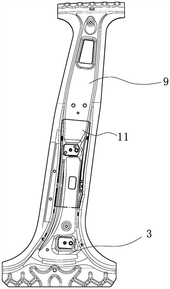
[0041] Such as figure 2 As shown, the technical solution of embodiment 2 is basically the same as the technical solution of embodiment 1, the difference is that the first heavy-duty intrusion structure includes a weakening ditch arranged at the lower end of the B-pillar body 1 close to the upper edge of the outer threshold 4 structure 3, the setting of the weakened groove-like structure 3 makes the B-pillar body 1 pendulum deformation mode when the vehicle is hit When it is lower, it can prevent the upper end of the B-pillar from causing damage to the driver's head and improve the safety of the vehicle.

Embodiment 3

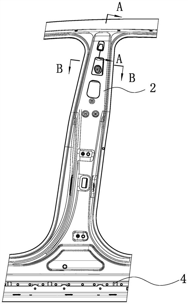
[0043] Such as image 3 , Figure 5 As shown, the technical solution of embodiment 3 is basically the same as the technical solution of embodiment 1, the difference is that: the second anti-deformation structure includes the first groove 601 arranged on the face recognition reinforcement plate 6, arranged on the The second groove 503 on the B-pillar inner panel 5 and the convex structure 504 arranged on the second groove 503, the convex structure 504 is arranged on the bottom surface of the second groove 503 close to the first groove 601, and the first concave The groove 601 and the second groove 503 are set in the same direction, and the position of the convex structure 504 corresponds to the first groove 601, which makes the convex structure 504 and the first groove 601 form an opposing anti-deformation structure, and a collision occurs on the B-pillar body 1 , the first groove 601 on the face recognition board deforms first, and after the deformation, the first groove 601 ...


PUM


Abstract

The invention discloses a B-pillar structure for installing a face recognition device, which includes a B-pillar body, and the B-pillar body includes a mounting assembly, a side wall outer panel connected sequentially through the mounting assembly from outside to inside, and a reinforcement plate assembly and an inner panel assembly, the reinforcement panel assembly includes a side sill reinforcement panel and a B-pillar reinforcement panel, the inner panel assembly includes a side sill inner panel and a B-pillar inner panel arranged in sequence from top to bottom, and the B-pillar reinforcement panel It also includes a face recognition reinforcement plate, which is fixed between the B-pillar reinforcement plate and the B-pillar inner panel; the B-pillar body is provided with an installation groove for installing a face recognition device and for raising Double reinforcement structure for B-pillar body strength. The invention provides a B-pillar structure for installing a face recognition device. The face recognition device is installed on the outer side of the B-pillar to make the vehicle intelligent while meeting the strength and stiffness requirements of the B-pillar and improving vehicle safety.

Description

technical field [0001] The invention relates to auto parts, in particular to a B-pillar structure for installing a face recognition device. Background technique [0002] With the rapid development of my country's automobile industry, people have higher and higher requirements for automobiles, higher and higher requirements for intelligence and human-computer interaction, and a deeper understanding of collision safety and other performances, especially in the era of intelligentization of everything. The demand for intelligence in all aspects of automobiles is particularly prominent. At present, domestically listed cars basically do not install intelligent face recognition systems on the B-pillars. Generally, the upper end of the B-pillar is connected to the top side beam, and the lower end is connected to the outer threshold. When installing the intelligent face recognition system on the B-pillar, considering the convenience of the man-machine, the face recognition device need...

Claims


Application Information

Patent Timeline
Patent Type & Authority Patents(China)
IPC IPC(8): B62D25/04G06K9/00
CPCB62D25/04G06V40/16
Inventor 刘建胜
Owner ZHEJIANG LEAPMOTOR TECH CO LTD
Why Eureka
Try Eureka