Solar energy heliostat gearing device

A transmission device and heliostat technology, applied in the field of transmission devices, can solve the problems of not being suitable for large-scale manufacturing and popularization, increasing the number of parts and structural dimensions, and high requirements for hydraulic system maintenance, so as to save manpower, save space, and ensure Effects on Safety and Reliability

Inactive Publication Date: 2008-09-10
BEIHANG UNIV
View PDF0 Cites 19 Cited by
  • Summary
  • Abstract
  • Description
  • Claims
  • Application Information

AI Technical Summary

Problems solved by technology

The hydraulic system has high requirements for maintenance, and the working oil should always be kept clean. The efficiency of the transmission system is low, the maximum efficiency is about 70%, and it is sensitive to oil temperature changes. It is not suitable to work at very high or very low temperatures. Poor stability, unable to meet the requirements of all-weather work
Due to the small single-stage transmission ratio of the backlash-free gear transmission structure, generally less than 5, multi-stage transmission is required for large output loads, which increases the number of parts and structural dimensions, resulting in high manufacturing costs and reduced transmission efficiency. cannot be used in the heliostat drive
Therefore, hydraulic transmission and backlash-free gear transmission are not suitable for large-scale manufacturing and popularization in large-area heliostat systems

Method used


Image

  • Solar energy heliostat gearing device
  • Solar energy heliostat gearing device
  • Solar energy heliostat gearing device

Examples


Embodiment Construction

[0026] The present invention will be further described below in conjunction with the accompanying drawings and specific embodiments.

[0027] The present invention uses tower type solar energy 100m 2 Take a heliostat drive as an example.

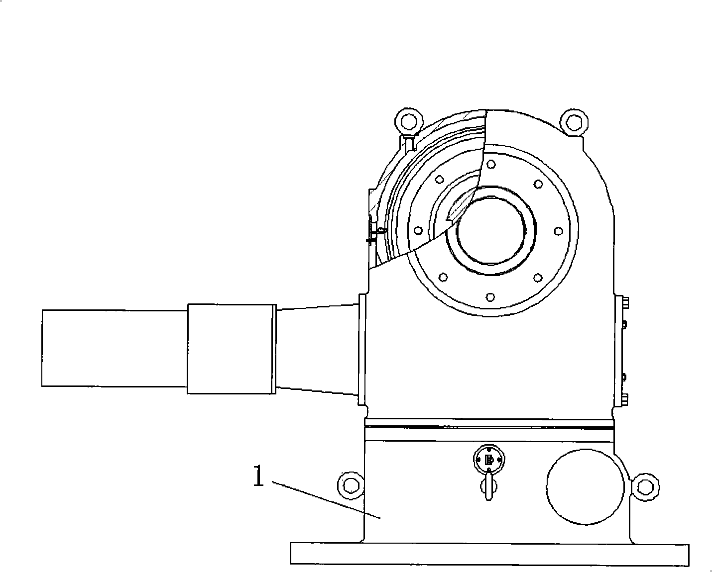
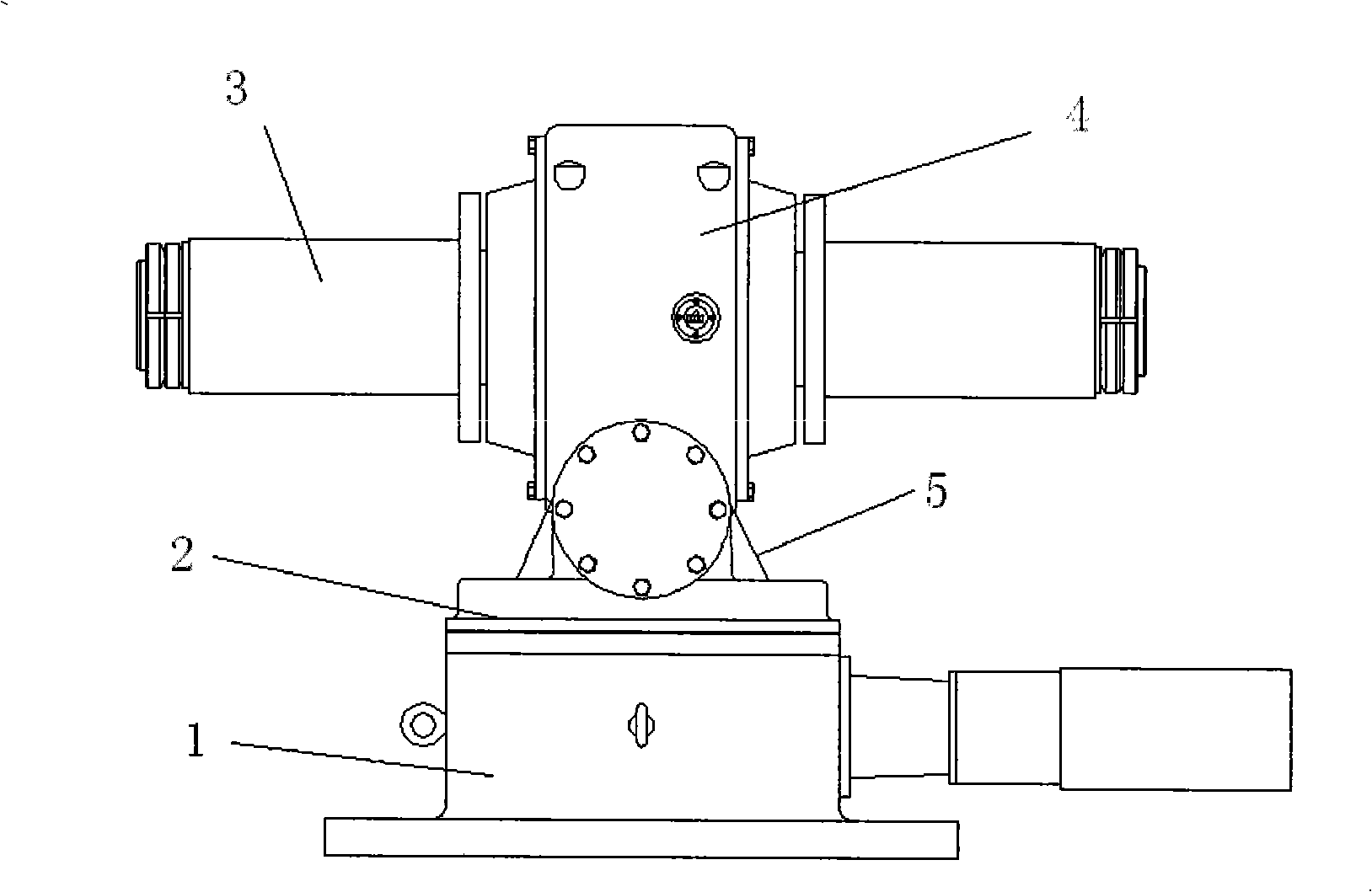
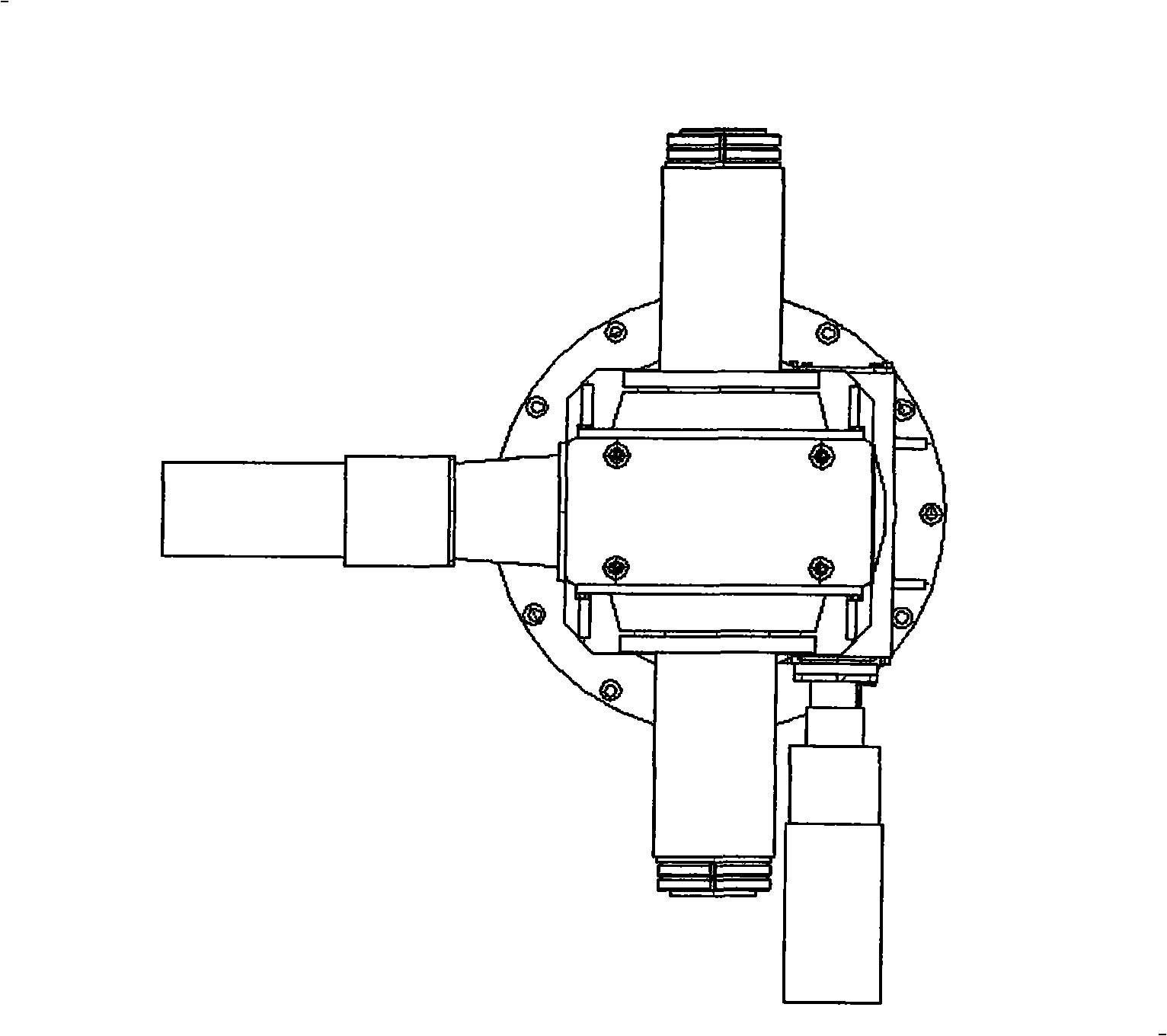
[0028] The overall structure of the solar heliostat transmission device of the present invention is as follows: figure 1 , 2 , as shown in 3, where figure 1 It is the front view of the solar heliostat transmission device of the present invention; figure 2 It is the left view of the solar heliostat transmission device of the present invention; image 3 It is a top view of the appearance of the solar heliostat transmission device of the present invention. The transmission device includes a lower box assembly 1 , a rotating mechanism 2 and an upper box assembly 4 . Among them, the upper box assembly 4 and the lower box assembly 1 are both processed and manufactured from steel materials, and the structure and wall thickness have been stri...


PUM


Abstract

The invention relates to a solar heliostat transmission gear, which comprises an upper box body component, a lower box body component and a rotary mechanism which connects the upper box body component and the lower box body component into a whole, wherein, the rotary mechanism comprises a spline groove which is matched and connected with a lower worm wheel shaft in the lower box body component and is arranged in the center of an upper box body bottom surface of the upper box body component, and the lower worm wheel shaft drives the upper box body component to move through the spline groove. Moreover, a gap fine adjustment structure is respectively arranged on both shaft ends of an upper worm wheel shaft in the upper box body component and the lower worm wheel shaft in the lower box body component and comprises an end bearing, a transparent cover and a threaded sleeve, wherein, the end bearing is arranged on the end part of the upper worm wheel shaft or the lower worm wheel shaft; the transparent cover is fixed together with an upper box body or a lower box body, and an inner ring of the transparent cover is provided with threads; and the threaded sleeve is arranged inside the transparent cover and externally provided with threads which are matched with the threads of the inner ring of the transparent cover, and tightly presses on the end bearing. The solar heliostat transmission gear not only has simple transmission form, high transmission efficiency and good maintainability, but also has long service life and low manufacturing and maintenance costs.

Description

technical field [0001] The invention relates to a transmission device, in particular to a solar heliostat transmission device applied to a tower type solar heliostat. Background technique [0002] A heliostat is a concentrating device consisting of a mirror (mirror), a mirror frame (supporting structure), a tracking transmission mechanism and its control system, etc. Inside the heater, it is one of the main devices of the tower solar thermal power station. The transmission mechanism is responsible for the movement and positioning functions of the heliostat in the heliostat system, and its performance directly determines the working efficiency of the heliostat, thus affecting the power generation efficiency of the entire system. Therefore, the heliostat transmission mechanism is a key part of the solar power generation system. [0003] The main basis for the selection of the transmission system is: the minimum power consumption, good tracking accuracy, the lowest manufactur...

Claims


Application Information

Patent Timeline
Patent Type & Authority Applications(China)
IPC IPC(8): F24J2/38G05D3/00F24S50/20
CPCF24J2/54F24J2002/5482Y02E10/47F24S2030/15F24S30/40
Inventor 王延忠祖伟雷震天王涛周元子吴灿辉
Owner BEIHANG UNIV
Why Eureka
Try Eureka