
Yarn storage tubes for textile machine stations and textile machine stations

A technology for yarn storage tubes and textile machines, applied in the field of yarn storage tubes, which can solve problems such as structural defects of yarn monitors, achieve high station productivity and improve station efficiency

Active Publication Date: 2022-04-15
SAURER SPINNING SOLUTIONS GMBH & CO KG
View PDF10 Cites 0 Cited by
  • Summary
  • Abstract
  • Description
  • Claims
  • Application Information

AI Technical Summary

Problems solved by technology

In addition, the use of a separate yarn monitor also has structural drawbacks in the station design

Method used


Image

  • Yarn storage tubes for textile machine stations and textile machine stations
  • Yarn storage tubes for textile machine stations and textile machine stations
  • Yarn storage tubes for textile machine stations and textile machine stations

Examples


Embodiment Construction

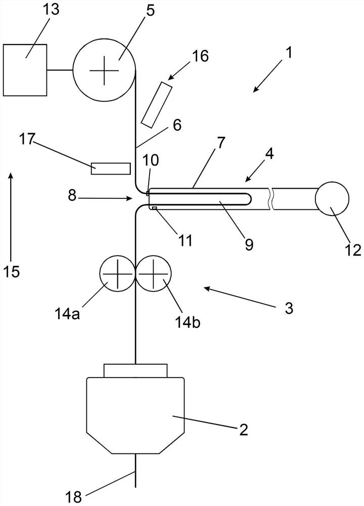
[0052] figure 1 A schematic diagram is shown of the station 1 with the yarn 6 extending from the spinning unit 2, for example an air spinning unit or a rotor spinning unit, to the yarn winding device 5 during the spinning process. The fiber slivers 18 supplied to the spinning unit 2 are drawn in the spinning unit 2 after passing through a drafting device not shown here in the case of an air spinning machine or an opening unit in the case of a rotor spinning machine. Twist.

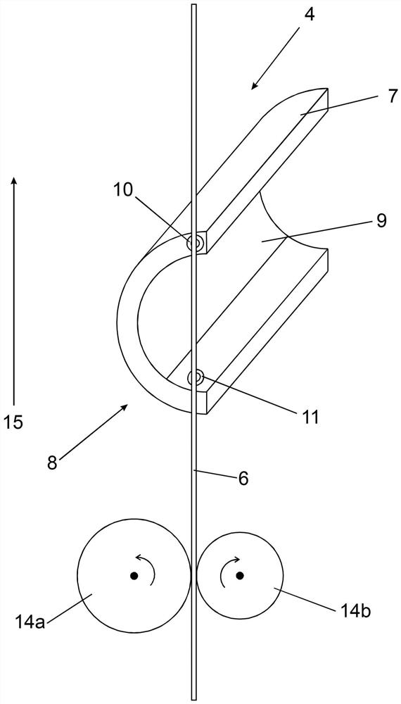
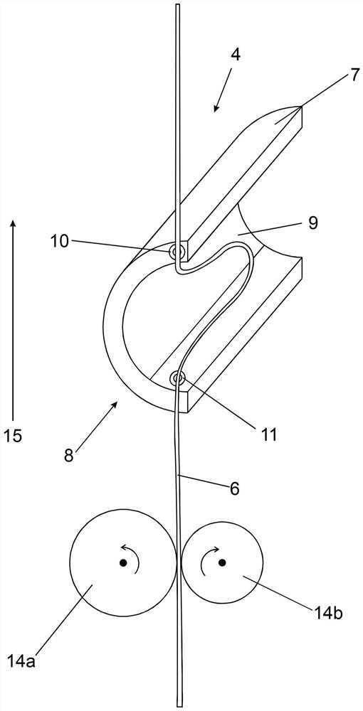
[0053] With regard to the direction of yarn movement 15, after the spinning unit 2 there is an unwinding device 3 which takes the yarn from the spinning unit 2 from the spinning unit by means of two unwinding rollers 14a, 14b forming a pair of unwinding rollers. The yarn unit 2 is withdrawn and fed to the yarn winding device 5 . Arranged after the unwinding device 3 is a yarn accumulator 4 with a yarn accumulator 7, on which a first yarn sensor 10 and a second yarn sensor 11 are integrated in the region ...


PUM


Abstract

The invention relates to a yarn storage tube for a textile machine station and a textile machine station, the station has a yarn storage device for temporarily storing part of the yarn and a yarn winding device arranged behind the yarn storage device. In order to provide a yarn accumulator for a textile machine station with a yarn winding device and a spinning machine station, wherein the station allows reliable monitoring of the yarn travel distance and a compact design of the station, it is specified for the yarn accumulator, The first yarn sensor, which is arranged in the region of the yarn inlet, is integrated in such a way that it monitors the yarn travel distance in the region in front of the yarn inlet. Provision is made for the station that the yarn accumulator has a yarn accumulator tube, which is arranged with a yarn inlet in the region of the yarn travel path, and which is subjected to the action of an air flow directed from the yarn inlet into the yarn accumulator tube. A first yarn sensor is integrated on the yarn accumulator in the inlet region so that it monitors the yarn travel distance in the region in front of the yarn inlet.

Description

technical field [0001] The invention relates to a thread accumulator tube for a textile machine station with a yarn winding device and a textile machine station with a thread accumulator for temporary storage of a thread portion and a Yarn winding device installed behind the yarn accumulator. Background technique [0002] Known textile machines have a number of stations of the type mentioned in the introduction arranged next to one another, at which the yarn is wound into bobbins, for example cross-wound bobbins. Thus, for example, on a spinning machine, a yarn is produced from a fed fiber sliver, and after leaving the spinning unit, the yarn passes successively as viewed in the direction of yarn movement, that is, as viewed in the direction of yarn delivery, through successively arranged withdrawals. The winding device and the yarn accumulator are finally wound on the yarn winding device. In this case, it is not necessary to arrange the yarn winding device and the yarn ac...

Claims


Application Information

Patent Timeline
Patent Type & Authority Patents(China)
IPC IPC(8): B65H51/22B65H63/00B65H51/08
CPCB65H51/22B65H63/00B65H51/08B65H2701/31B65H51/205B65H63/065
Inventor S·托马斯克劳迪娅·佳尔维茨克里斯托夫·哈泽
Owner SAURER SPINNING SOLUTIONS GMBH & CO KG
Learn More