Light conversion element, lens assembly, and electronic device
A technology for optical conversion components and electronic equipment, applied in electrical components, televisions, color televisions, etc., can solve problems such as inability to display at the opening, poor display effect on the display screen, and the opening of the display screen cannot be too small, etc., to achieve Save the transmission path, reduce the size of the opening, and save the installation space
- Summary
- Abstract
- Description
- Claims
- Application Information
AI Technical Summary
Problems solved by technology
Method used
Image

Examples
no. 2 example
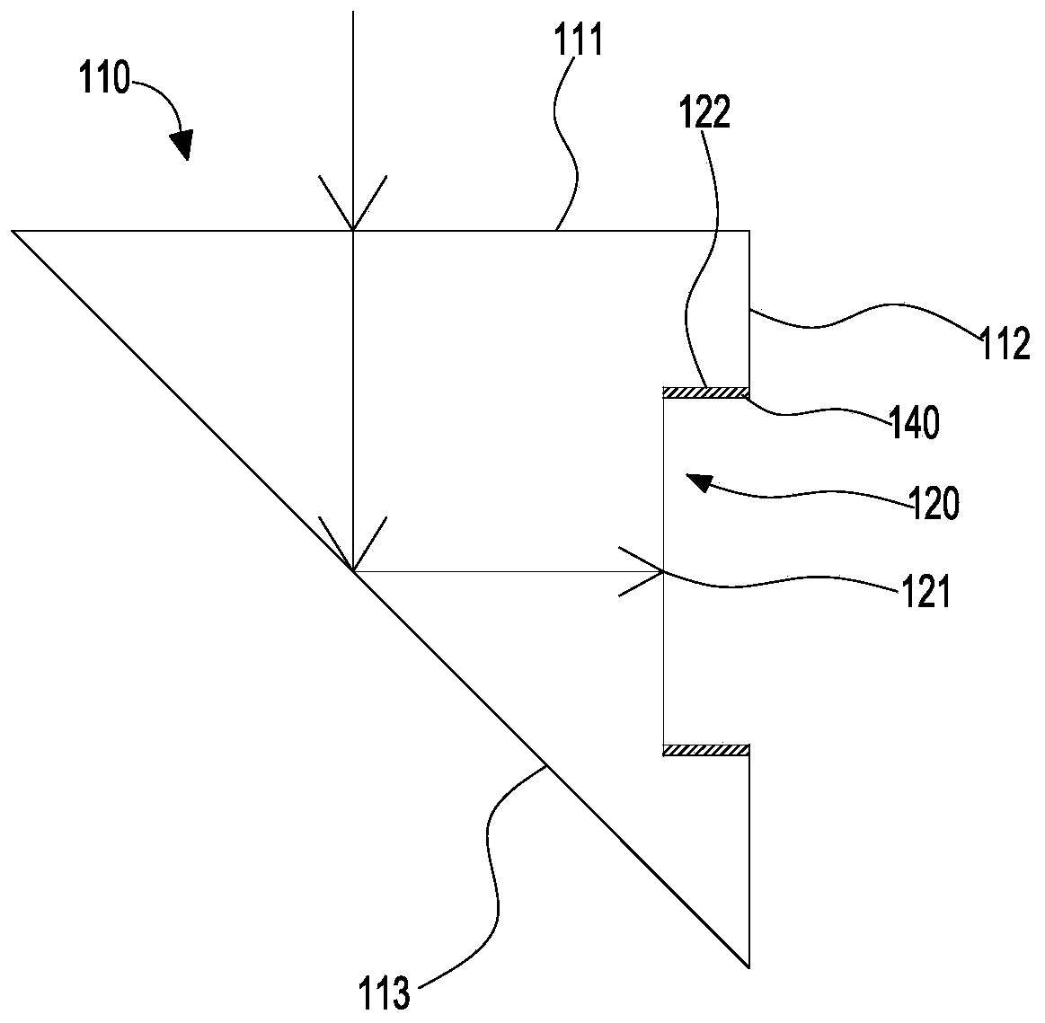
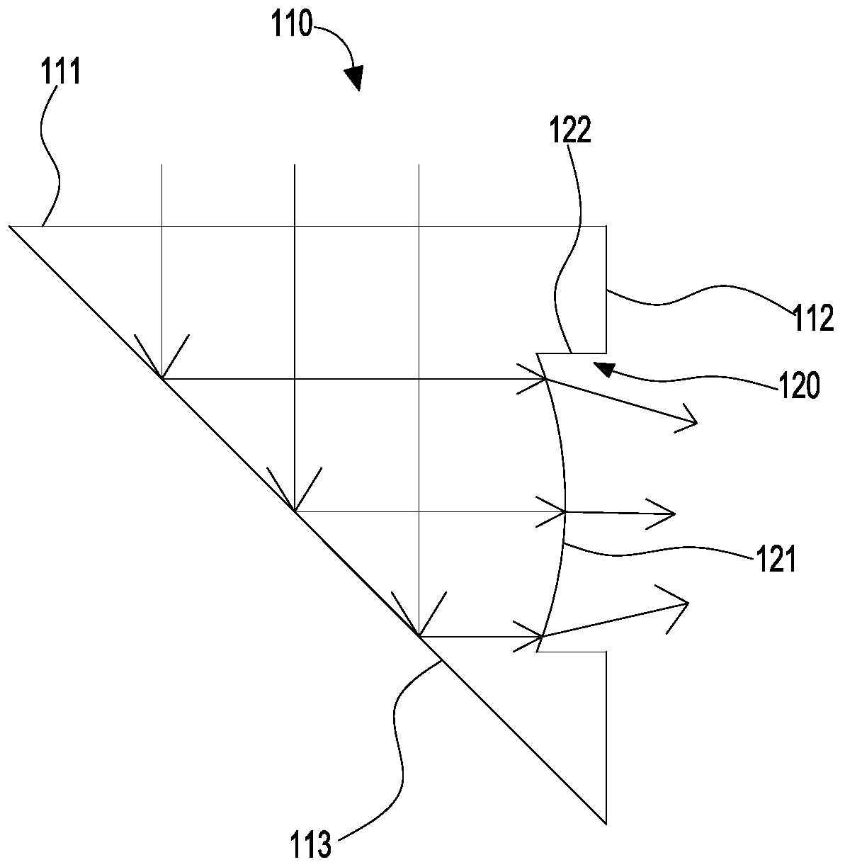
[0039] As another implementation, see image 3 , image 3 shows another light conversion element 100 structure, with figure 1 Compared with the light converting element 100 shown, the difference lies in that the structure of the bottom surface 121 in this embodiment is different. For the same parts, reference may be made to the relevant content of the first embodiment, and details are not repeated here.
[0040] refer to image 3 , in this embodiment, the bottom surface 121 is a convex surface protruding toward the side of the image sensor 200, the convex surface can play the role of converging light, and can converge the light reflected by the first reflective surface 113 into the accommodation groove 120 Convergence, which plays the role of concentrating light, so that the light rays converged into the accommodation groove 120 can all enter the lens 210 extending into the accommodation groove 120, improve the utilization rate of light, and also enable the image sensor to ...
no. 3 example
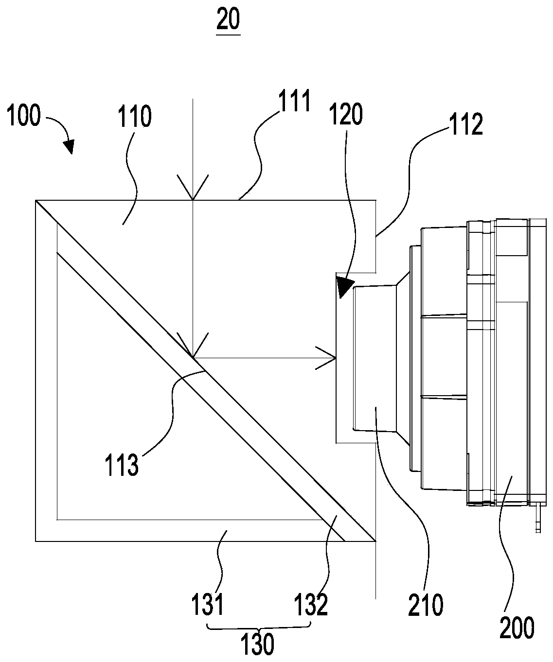
[0045] refer to Figure 5 This embodiment provides a lens assembly 20, including a light conversion element 100 (not marked in the figure) and an image sensor 200. The difference from the first embodiment is that in this embodiment, the structure of the light conversion element 100 is different.
[0046] In this embodiment, the light conversion element 100 includes a prism 110, which is a roughly quadrangular prism structure. The prism 110 has a light incident surface 111 and a light exit surface 112. The prism 110 also includes a first reflective surface 113 and a second reflective surface 113. On the surface 114 , when the light enters the prism 110 from the light incident surface 111 , it is reflected by the first reflective surface 113 and enters the second reflective surface 114 , and is reflected by the second reflective surface 114 and exits from the light output surface 112 . That is, when light enters the prism 110 from the light incident surface 111 , it is reflected...
no. 4 example
[0053] refer to Figure 6 , this embodiment provides an electronic device 10, the electronic device 10 includes a casing 11, a display screen 30 and the lens assembly 20 shown in the first embodiment, wherein the display screen 30 is assembled on the casing 11 and exposed, and the lens assembly 20 It is arranged inside the housing 11.
[0054] The casing 11 includes a middle frame (not shown), a front case (not shown) and a rear cover (not shown), the front case and the rear cover are assembled on opposite sides of the middle frame, and are connected to the middle frame An accommodating space for accommodating various components is formed, the lens assembly 20 is accommodated in the accommodating space, and the display screen 30 is installed on one side of the casing where the front case is provided and assembled with the front case.
[0055] A light-transmitting portion 34 is disposed on the display screen 30 , so that light can enter the accommodation space through the ligh...
PUM
 Abstract
Description
Claims
Application Information
 - R&D
- Intellectual Property
- Life Sciences
- Materials
- Tech Scout
- Unparalleled Data Quality
- Higher Quality Content
- 60% Fewer Hallucinations
Browse by: Latest US Patents, China's latest patents, Technical Efficacy Thesaurus, Application Domain, Technology Topic, Popular Technical Reports.
© 2025 PatSnap. All rights reserved.Legal|Privacy policy|Modern Slavery Act Transparency Statement|Sitemap|About US| Contact US: help@patsnap.com