Floor wireway slotting device

A wire pipe and floor technology, which is applied in the field of floor wire pipe slotting devices, can solve the problems of easy dust generation and low work efficiency, and achieve the effect of helping to cool down

Active Publication Date: 2020-08-21
HUAREN CONSTR GROUP
View PDF5 Cites 0 Cited by
  • Summary
  • Abstract
  • Description
  • Claims
  • Application Information

AI Technical Summary

Problems solved by technology

[0004] In order to overcome the shortcomings of dust and low work efficiency when workers are working, the technical problem of the present invention is to provide a floor wire and duct slotting device that can help workers block dust and cool down the cutting knife when slotting

Method used


Image

  • Floor wireway slotting device
  • Floor wireway slotting device
  • Floor wireway slotting device

Examples


Embodiment 1

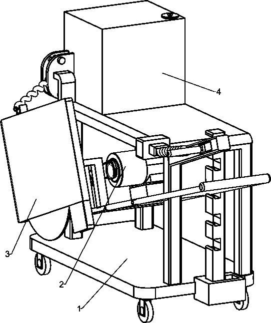
[0050] A kind of slotting device for electric wires and pipes on the floor, such as figure 1 As shown, a mounting device 1 and a cutting mechanism 2 are included, and the cutting mechanism 2 is connected to the mounting device 1 .

[0051] When a worker needs to make a groove on the floor wire duct, the worker first pushes the installation device 1 to drive the cutting mechanism 2 to move, so that the parts of the cutting mechanism 2 are aligned with the position where the groove needs to be made, and then the worker starts the cutting mechanism 2 to make the cutting mechanism 2 open. slot, while the worker pushes the installation device 1 to drive the cutting mechanism 2 to move, so that the parts of the cutting mechanism 2 are slotted while moving to open the floor wire and duct groove.

Embodiment 2

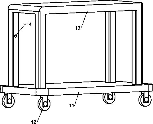
[0053] On the basis of Example 1, such as Figure 2-3 As shown, the installation device 1 includes an installation base plate 11, an installation wheel 12 and an installation frame 13, the four corners of the bottom of the installation base plate 11 are rotatably connected with the installation wheels 12, the top of the installation base plate 11 is provided with an installation frame 13, and the front side of the middle part of the installation frame 13 A fixing hole 14 is provided, and the parts of the cutting mechanism 2 are connected to the fixing hole 14 in a rotational manner.

[0054] When a worker needs to slot the wire duct on the floor, the worker first pushes the installation frame 13 so that the installation wheel 12 rotates to drive the cutting mechanism 2 to move, so that the parts of the cutting mechanism 2 are aligned with the position that needs to be slotted, and then the worker starts the cutting mechanism 2, Cutting mechanism 2 is slotted, and the workman p...

Embodiment 3

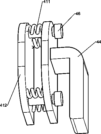
[0058] On the basis of Example 2, such as Figure 4-6 As shown, include dust-proof mechanism 3, dust-proof mechanism 3 also includes dust-proof rack 31, dust-proof block 32 and sliding block 35, fixed frame 21 left fronts are provided with two dust-proof blocks 32, two dust-proof blocks 32 front parts are provided with dust-proof frame 31, have through-hole 33 in the middle part of dust-proof frame 31 rear sides, cutting shaft 29 passes through-hole 33, cutting knife 26 is inside dust-proof frame 31, and dust-proof frame 31 tops have square Groove 34, sliding block 35 is connected with sliding on the square groove 34.

[0059] When the worker is cutting the ground groove, the dust-proof frame 31 makes the dust during cutting inside the dust-proof frame 31, and then leaks from the bottom of the dust-proof frame 31, which will not hinder the workman's sight and make the worker inhale the dust to affect his health.

[0060] Also include sprinkler mechanism 4, sprinkler mechanism...


PUM


Abstract

The invention relates to a slotting device, in particular to a floor wireway slotting device. The floor wireway slotting device aims to achieve the technical purposes of being capable of assisting workers in shielding dust and cooling a cutter during slotting by the workers. According to the technical implementation scheme, the floor wireway slotting device comprises an installation device and a cutting mechanism, and the cutting mechanism is connected to the installation device; and optionally, the installation device comprises an installation bottom plate, installation wheels and an installation frame, wherein the installation wheels are rotationally connected to the four corners of the bottom of the installation bottom plate, the installation frame is arranged on the top of the installation bottom plate, a fixing hole is formed in one side of the middle of the installation frame, and a component of the cutting mechanism is rotationally connected with the fixing hole. When the workers cut the ground for slotting, a dustproof frame enables dust produced during cutting to be contained in the dustproof frame and leaked from the bottom of the dustproof frame, and the problems that the sight of the workers is blocked and the workers inhale dust to affect health are avoided.

Description

technical field [0001] The invention relates to a grooving device, in particular to a grooving device for floor electric wire ducts. Background technique [0002] At present, workers usually use the cutting knife of the cutting machine to directly contact the ground when making grooves for electric wire ducts. This not only makes the workers have a lot of dust when cutting, which interferes with the workers' grooves and causes the workers to inhale dust to affect their health. The temperature of the knife increases due to friction, which affects the work of the workers. [0003] Therefore, it is necessary to study a floor wire duct slotting device that can help workers block dust and cool down the cutting knife when workers are slotting, to overcome the fact that when workers are cutting, the dust is very large, which interferes with the work of the workers and causes the workers to inhale the dust and affect their health. , and the temperature of the cutting knife increase...

Claims


Application Information

Patent Timeline
Patent Type & Authority Applications(China)
IPC IPC(8): B28D1/24B28D7/02B28D7/00
CPCB28D1/24B28D7/02B28D7/00Y02W30/82
Inventor 周建勋
Owner HUAREN CONSTR GROUP
Why Eureka
Try Eureka