
A sewage collection device and collection method for a saturation diving ship

A sewage collection and sewage technology, which is applied in the direction of engine room flushing device, ship soil drainage, and living quarters, can solve the problems of high decompression costs, inability to install domestic sewage collection devices, and difficult discharge of domestic sewage, so as to improve safety, The effect of avoiding environmental pollution

Active Publication Date: 2021-05-11
CSSC HUANGPU WENCHONG SHIPBUILDING COMPANY
View PDF9 Cites 0 Cited by
  • Summary
  • Abstract
  • Description
  • Claims
  • Application Information

AI Technical Summary

Problems solved by technology

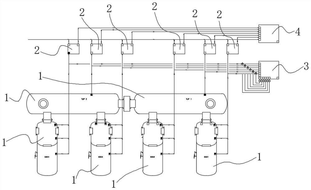
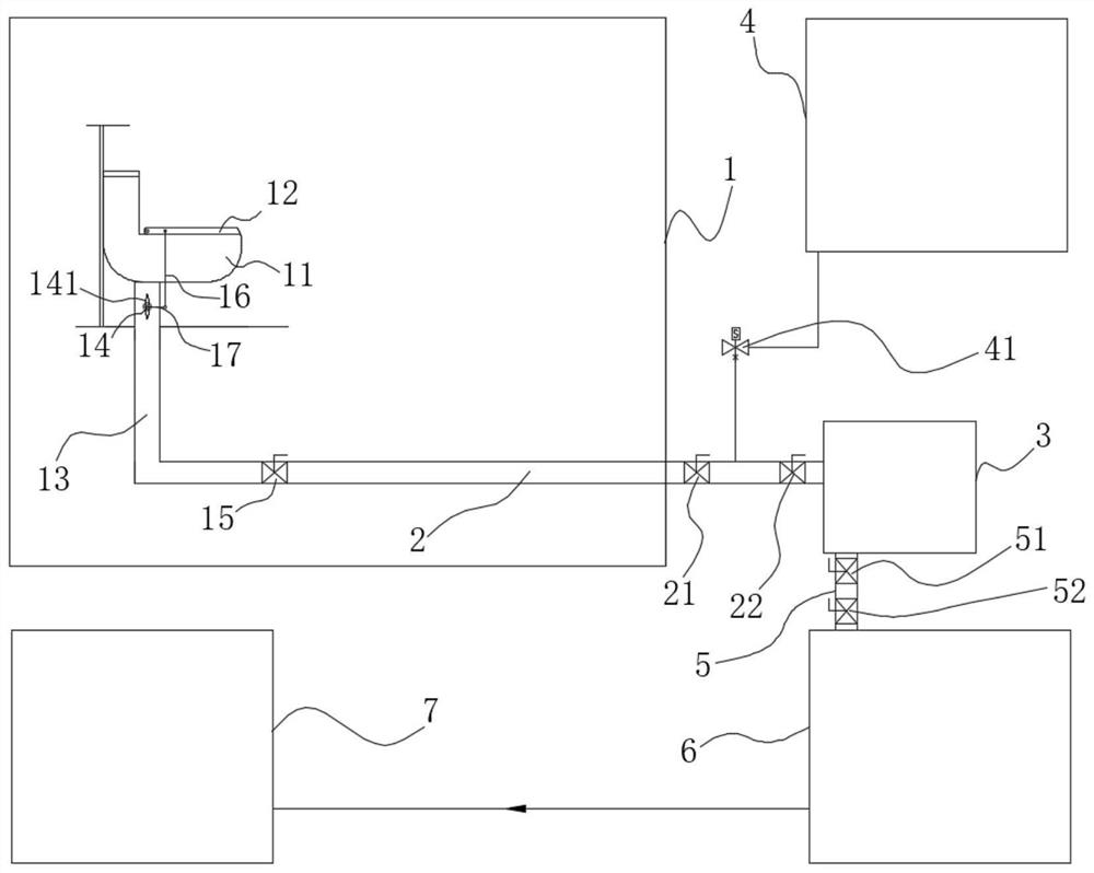
[0002] The hyperbaric chamber (decompression chamber (DDC), transition chamber (TUP)) in a saturation diving boat is a hyperbaric chamber that theoretically divers can live in for a long time. A resting place during the decompression waiting period after the completion of the diving operation, and because of the special nature of the diving operation, the cost of decompression and decompression is relatively expensive, so sometimes even after the diver completes the diving operation, he will not decompress and exit the cabin immediately but continue to wait in the hyperbaric chamber , and the hyperbaric chamber is a confined space with high pressure and airtightness, and it is impossible to install a domestic sewage collection device. The domestic water needs to be discharged to the normal pressure environment outside the cabin for collection. The resulting pressure difference discharges the domestic sewage out of the cabin, but when the hyperbaric chamber is at low pressure (such as the initial stage of pressurization of the hyperbaric chamber and the end of decompression of the hyperbaric chamber), it is difficult to discharge the domestic sewage from the hyperbaric chamber to the outside of the cabin

Method used


Image

  • A sewage collection device and collection method for a saturation diving ship
  • A sewage collection device and collection method for a saturation diving ship
  • A sewage collection device and collection method for a saturation diving ship

Examples


Embodiment Construction

[0029] The specific implementation manners of the present invention will be further described in detail below in conjunction with the accompanying drawings and embodiments. The following examples are used to illustrate the present invention, but are not intended to limit the scope of the present invention.

[0030] In the description of the present invention, it should be understood that the orientation or positional relationship indicated by the terms "upper", "lower", "left", "right", "top", "bottom" etc. Orientation or positional relationship is only for the convenience of describing the present invention and simplifying the description, and does not indicate or imply that the referred device or element must have a specific orientation, be constructed and operated in a specific orientation, and thus should not be construed as a limitation of the present invention. It should be understood that the terms "first", "second", etc. are used in the present invention to describe va...


PUM


Abstract

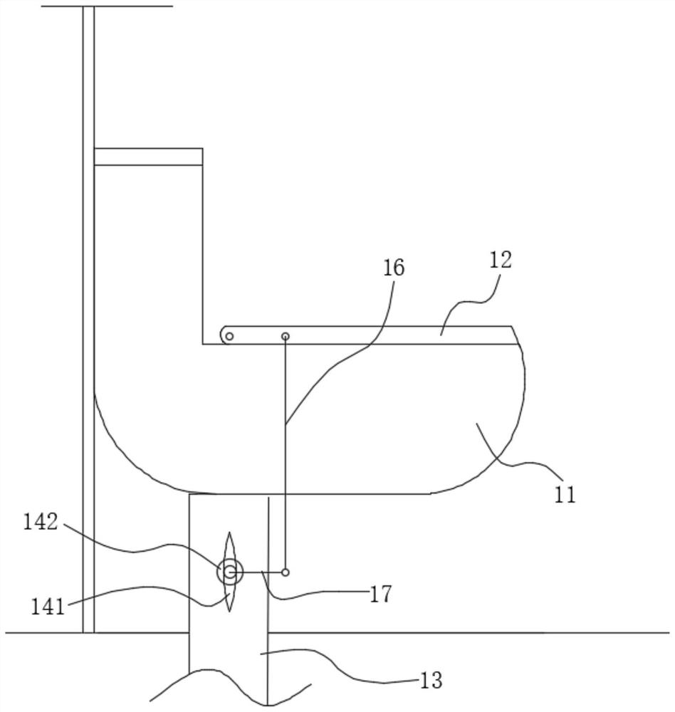
The invention relates to the technical field of diving equipment, and discloses a sewage collection device for a saturated diving ship, which is provided with a first sensor and a hyperbaric chamber of a toilet, and a first valve and a first normally closed reset valve are provided on the sewage discharge pipe of the toilet. A second valve and a third valve are arranged between the sewage pipe and the sewage tank provided with the second sensor, the vacuum pump is connected with the sewage tank, the sewage tank is connected with the sewage collection box through the second connecting pipe, and a saturated diving In the collection method of the ship's sewage collection device, the main controller controls the start and stop of the vacuum pump according to the air pressure in the hyperbaric cabin and the air pressure in the sewage tank. The invention can make the hyperbaric cabin in a low-pressure state, and can still efficiently collect sewage. Discharge to the outside of the cabin, high safety, and does not destroy the airtightness of the hyperbaric cabin.

Description

technical field [0001] The invention relates to the technical field of diving equipment, in particular to a sewage collection device and a collection method for a saturation diving ship. Background technique [0002] The hyperbaric chamber (decompression chamber (DDC), transition chamber (TUP)) in a saturation diving boat is a hyperbaric chamber that theoretically divers can live in for a long time. A resting place during the decompression waiting period after the completion of the diving operation, and because of the special nature of the diving operation, the cost of decompression and decompression is relatively expensive, so sometimes even after the diver completes the diving operation, he will not decompress and exit the cabin immediately but continue to wait in the hyperbaric chamber , and the hyperbaric chamber is a confined space with high pressure and airtightness, and it is impossible to install a domestic sewage collection device. The domestic water needs to be dis...

Claims


Application Information

Patent Timeline
Patent Type & Authority Patents(China)
IPC IPC(8): B63B29/16B63B29/14
CPCB63B29/14B63B29/16
Inventor 宋士虎刘崇喆伍常斌陈超潘国华冯仕清
Owner CSSC HUANGPU WENCHONG SHIPBUILDING COMPANY
Learn More