Sealing device having ambient sensing and data transmission

A technology for data transmission and sealing devices, applied in electrical components, semiconductor/solid-state device manufacturing, circuits, etc., can solve problems such as wafer corrosion, unsustainable monitoring, and technical personnel reference

Inactive Publication Date: 2016-08-10
刘淑真
View PDF4 Cites 6 Cited by
  • Summary
  • Abstract
  • Description
  • Claims
  • Application Information

AI Technical Summary

Problems solved by technology

[0006] Unable to securely save the wafer
[0007] The existing sampling mechanism is to form an opening on the inner part and the outer part, so that the inside of the main body communicates with the external environment, so as to obtain the air inside the main body, but the opening does allow the outside air to enter the delivery box. Contamination caused by internal gas cannot reliably preserve the quality of wafers placed in the pod
[0008] unable to monitor continuously
[0009] The existing sampling mechanism is a transfer box corresponding to a sampling mechanism, which is two separate devices connected together by a transmission line to obtain the information in the transfer box, when the transfer box must be transported long distances, the sampling The mechanism cannot move with the teleportation box, resulting in the inability to continuously monitor the environment inside the teleportation box
[0010] Unable to provide wafer information
[0011] The FOUP only samples and monitors the internal environment of the FOUP. There is no record of the wafers placed in the FOUP. When the internal environment changes and affects the quality of the wafer, the FOUP cannot provide wafer information. For technical reference
[0012] The existing technology is to use a perforated FOUP for sampling and monitoring of the internal air, which will cause the air inside the FOUP to be polluted, and the sampling monitoring cannot continuously monitor the sealing state of the FOUP. A gas accident caused water vapor inside the FOUP, and the relevant technical personnel could not be notified immediately to deal with it. We could only let the multiple wafers corrode and cause losses.

Method used


Image

  • Sealing device having ambient sensing and data transmission
  • Sealing device having ambient sensing and data transmission
  • Sealing device having ambient sensing and data transmission

Examples


Embodiment Construction

[0040] The present invention will be further described below in conjunction with specific examples, so that those skilled in the art can better understand the present invention and implement it, but the given examples are not intended to limit the present invention.

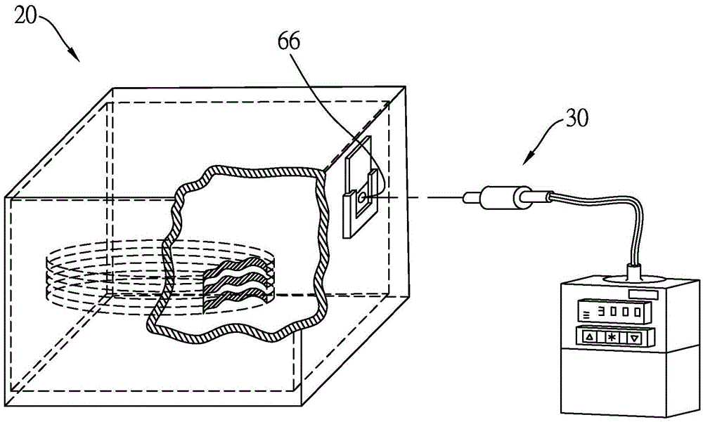
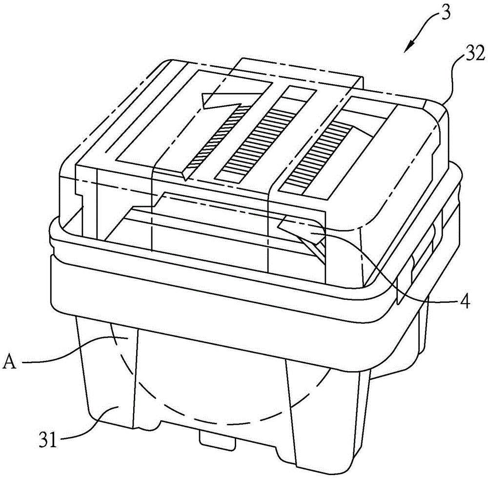
[0041] refer to figure 2 , image 3 , Figure 4 , is the first preferred embodiment of the sealing device with environmental sensing and data transmission of the present invention, and is suitable for carrying and transporting an item A. In the first preferred embodiment, the item A is a plurality of wafers, The sealing device includes a main body unit 3 , a carrying unit 4 and an information sensing unit 5 .

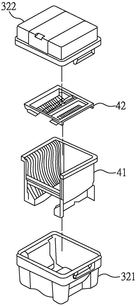
[0042] The main body unit 3 includes a main body 32 surrounding and defining an accommodating space 31 , the main body 32 has a first shell 321 , and a second shell 322 detachably assembled with the first shell 321 . The carrier unit 4 includes a carrier tray 41 arranged in the accommodating space 31 f...


PUM


Abstract

The invention discloses a sealing device having ambient sensing and data transmission. The sealing device is suitable for bearing and delivering at least one article, and comprises a main unit and an information sensing unit. The main unit comprises a main body that is enclosed to form an accommodation space. The information sensing unit comprises a sensor that is arranged in the accommodation space, and a first information transceiver that is electrically connected to the sensor. The sensor can detect environmental parameters of the accommodation space, the first information transceiver can send the environmental parameters, and thus people will acknowledge the state of the article in the accommodation space.

Description

technical field [0001] The present invention relates to a sealing device, in particular to a sealing device with environment sensing and data transmission. Background technique [0002] Regarding the wafers currently used in semiconductors, the wafers (Wafer) used in the crystal pulling factory are single crystal silicon rods drawn and extracted from silicon dioxide (SiO2) as a material, and then sliced ​​and polished into wafers. After the wafer is produced, it will be placed in a wafer shipping box (FOSB) filled with nitrogen gas, and then packed in an opaque plastic film. Finally, the air in the wafer shipping box and the plastic film will be pumped out to preserve The quality of the wafer is maintained for a period of time to avoid oxidation or deterioration of the wafer, and it is smoothly transported to the semiconductor factory for semiconductor manufacturing. [0003] The above-mentioned multiple wafers will be moved and placed in the front-opening wafer transfer bo...

Claims


Application Information

Patent Timeline
Patent Type & Authority Applications(China)
IPC IPC(8): H01L21/67H01L21/673
CPCH01L21/67242H01L21/67294H01L21/6735
Inventor 刘淑真
Owner 刘淑真
Why Eureka
Try Eureka