Thermal shaping jig

A thermal shaping and jig technology, applied in forming tools, manufacturing tools, metal processing equipment, etc., can solve problems such as product side crushing and product defects, and achieve the effect of improving product yield and avoiding crushing

Inactive Publication Date: 2020-08-25
华孚精密科技(马鞍山)有限公司
View PDF9 Cites 0 Cited by
  • Summary
  • Abstract
  • Description
  • Claims
  • Application Information

AI Technical Summary

Problems solved by technology

However, due to thermal expansion and contraction of the product, the s

Method used


Image

  • Thermal shaping jig
  • Thermal shaping jig

Examples


Example Embodiment

[0018] The technical solutions of the present invention will be further described below in conjunction with the drawings and specific implementations.

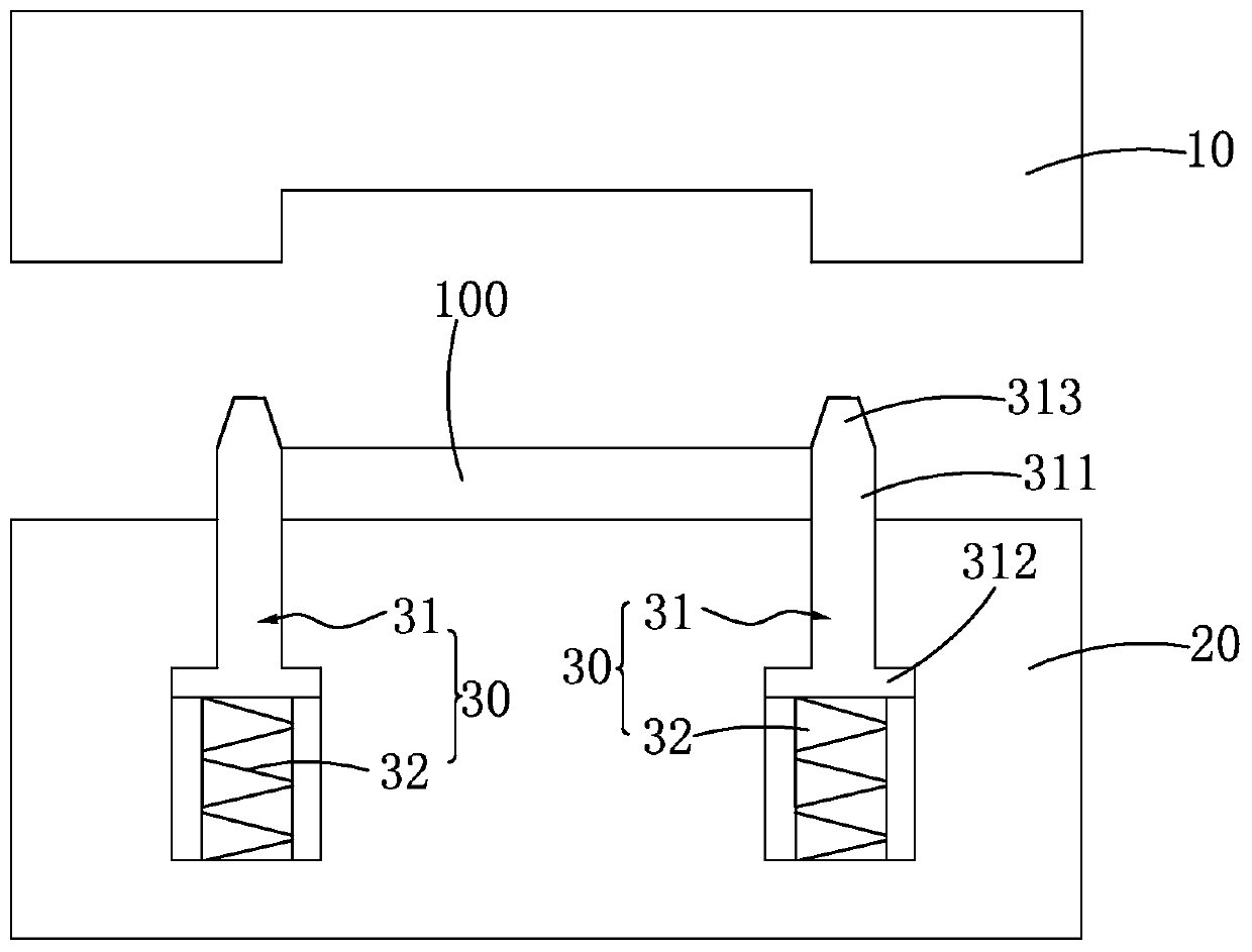
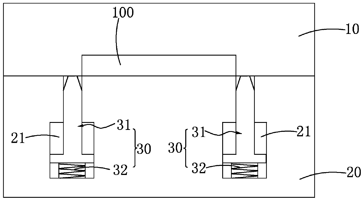
[0019] Such as Figure 1-2 As shown, a thermal shaping fixture includes an upper mold 10 and a lower mold 20; the lower mold 20 is provided with at least a pair of elastic positioning components 30 for positioning the product to be shaped 100; each elastic positioning component 30 includes a positioning column 31 And elastic piece 32. Wherein, the positioning column 31 is accommodated in the lower mold 20, and the top end of the positioning column 31 can move out of the lower mold 20 along the mold opening direction; the elastic member 32 is connected to the bottom surface of the positioning column 31 and can expand and contract along the mold opening direction. When the mold is opened, the positioning pillar 31 extends out of the lower mold 20 under the elastic force of the elastic member 32; when the mold is closed, the positi...


PUM


Abstract

The invention relates to the field of automation equipment, and particularly discloses a thermal shaping jig. The jig comprises an upper mold and a lower mold, wherein the lower mold is provided withat least one pair of elastic positioning assemblies for positioning a to-be-shaped product, and each elastic positioning assembly comprises a positioning column and an elastic piece, wherein the positioning columns are accommodated in the lower mold, and the top ends of the positioning columns can be movably extended out of the lower mold in a mold opening direction, the elastic pieces are connected to the bottom surfaces of the positioning columns and can stretch and draw back in the mold opening direction. During mold opening, the positioning columns can be extended out of the lower mold under elastic action of the elastic pieces; and during mold closing, the positioning columns are drawn into the lower mold under pressing of the upper mold and the elastic action of the elastic pieces. According to the thermal shaping jig, a product can be prevented from being extruded and damaged in a thermal shaping process, and the product yield is improved.

Description

【Technical field】 [0001] The invention relates to the technical field of thermal shaping mold fixtures, in particular to a thermal shaping fixture. 【Background technique】 [0002] After the die-casting molding is formed, it will be deformed to varying degrees due to reasons such as rapid cooling, material properties and product structure. For some products that require high dimensional accuracy, such as products that are used as appearance parts, they are usually heat-pressed and shaped with a heat-shaping fixture after forming. [0003] Existing thermoforming fixtures generally include an upper mold and a lower mold, and the product is flattened by the cooperation of the upper mold and the lower mold. In order to avoid product movement during thermal shaping, positioning columns are usually added to the lower die to position the product. However, due to thermal expansion and contraction of the product, the sides of the product are easily crushed, resulting in defective pr...

Claims


Application Information

Patent Timeline
IPC IPC(8): B21D37/12B21D3/00
CPCB21D3/00B21D37/12
Inventor 盛富強
Owner 华孚精密科技(马鞍山)有限公司
Why Eureka
Try Eureka