
Material transfer system

A material transfer and control system technology, applied in conveyor control devices, conveyors, conveyor objects, etc., can solve problems such as large product position deviation, and achieve the effect of ensuring position consistency

Inactive Publication Date: 2020-08-25
GUANGDONG MINGLIDA TECH
View PDF11 Cites 2 Cited by
  • Summary
  • Abstract
  • Description
  • Claims
  • Application Information

AI Technical Summary

Problems solved by technology

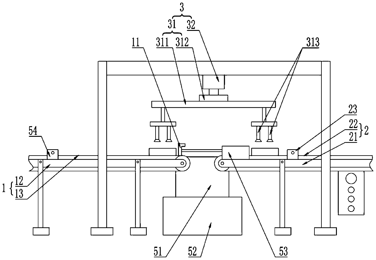
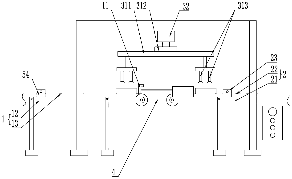
[0004] The purpose of the present invention is to provide a material transfer system to solve the problem in the prior art that when products are transferred from one conveying device to another conveying device, the position deviation of the product on the latter conveying device is large

Method used


Image

  • Material transfer system
  • Material transfer system

Examples


Embodiment Construction

[0032] In order to make the purpose, features and advantages of the present invention more obvious and understandable, the technical solutions in the embodiments of the present invention will be clearly and completely described below in conjunction with the accompanying drawings in the embodiments of the present invention. Obviously, the following The described embodiments are only some, not all, embodiments of the present invention. Based on the embodiments of the present invention, all other embodiments obtained by persons of ordinary skill in the art without making creative efforts belong to the protection scope of the present invention.

[0033] In the description of the present invention, it should be understood that the orientations or positional relationships indicated by the terms "upper", "lower", "top", "bottom", "inner" and "outer" are based on those shown in the accompanying drawings. Orientation or positional relationship is only for the convenience of describing ...


PUM


Abstract

The invention discloses a material transfer system. The material transfer system comprises a first conveying device and a second conveying device which are arranged in a spaced mode, and further comprises a grabbing and releasing device used for transferring products from the first conveying device onto the second conveying device. The grabbing and releasing device comprises a rotating device anda lifting device. The rotating device comprises a first driving device. A rotary shaft of the first driving device is fixedly connected with a fixed plate. The fixed plate is provided with a pluralityof suction cup assemblies used for grabbing and releasing the products. The material transfer system provided by the invention can stably and effectively transfer the products from the first conveying device onto the second conveying device through the set steps and facilitates achievement of mechanized production of the products.

Description

technical field [0001] The invention relates to the field of delivery of injection molding products, in particular to a material transfer system. Background technique [0002] In actual production, due to production needs, it is often necessary to transfer the product on one conveying device to another conveying device, so as to realize the assembly line production of the product. [0003] In the prior art, a higher conveying device and a lower conveying device are usually arranged, and a chute is arranged between the two conveying devices, and the products on the higher conveying device fall through the chute to the lower height. On the conveying device, so as to realize the purpose of transferring the product from one conveying device to another conveying device. The disadvantage of the prior art is that when the product passes through the chute, it often deviates or rotates, causing a large positional deviation of the product on the latter conveying device, which is not ...

Claims


Application Information

Patent Timeline
IPC IPC(8): B65G47/91B65G47/52B65G47/88B65G43/08
CPCB65G43/08B65G47/52B65G47/8815B65G47/915B65G2203/0266
Inventor 陶诚佘本龙邓全勇姚林平邓昶徐光周
Owner GUANGDONG MINGLIDA TECH
Learn More