Widened pulp pool structure for broke pulper

A pulper and pulp tank technology, which is applied in papermaking, paper recycling, textiles and papermaking, etc., can solve the problems of not making good use of the interaction of pulp flow, low efficiency of broken paper disintegration, and high energy consumption. Optimized design, strong paper interaction, and increased contact frequency

Active Publication Date: 2020-08-25
ZHENGZHOU LEIZHAN TECH PAPER MACHINERY
View PDF11 Cites 0 Cited by
  • Summary
  • Abstract
  • Description
  • Claims
  • Application Information

AI Technical Summary

Problems solved by technology

[0007] However, the above-mentioned technical scheme still utilizes the disintegration effect of the rotor of the pulper to work, and does not make good use of the interaction between laminar flow and turbulent flow in the pulp flow, and the disintegration efficiency of broken paper is low, the time is long, and the energy consumption is large.

Method used


Image

  • Widened pulp pool structure for broke pulper
  • Widened pulp pool structure for broke pulper
  • Widened pulp pool structure for broke pulper

Examples


Embodiment Construction

[0027] The specific implementation manners of the present invention will be described in detail below in conjunction with the accompanying drawings.

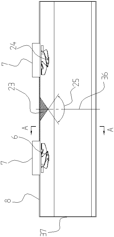
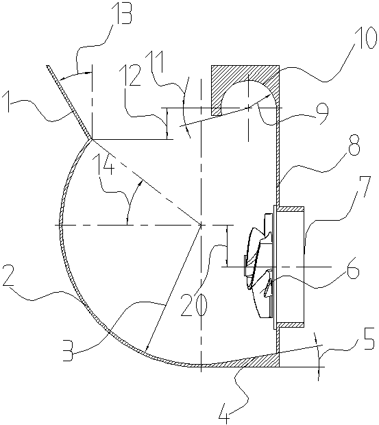
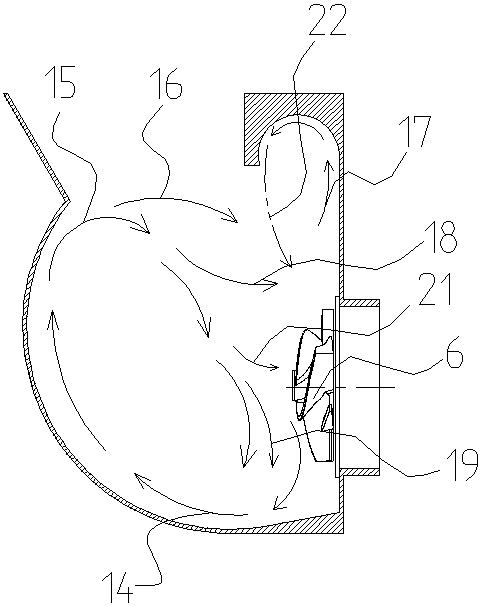
[0028] Such as Figure 1 to Figure 4 As shown, a widened pulp tank structure for broke pulper in this embodiment includes a pulp tank, a rotor is arranged in the pulp tank, and the pulp tank consists of a front side wall 2, a rear side wall 8, left and right side walls and The upper open structure formed by enclosing the pool bottom 4.

[0029] Such as figure 1 Shown is the top view of the present invention, in the center of the rear side wall 8 of the slurry tank, a diversion cone 23 is arranged, and the diversion cone 23 goes up to the whirling arc 10 and down to the bottom 4 of the tank. On its head is a sharp angle 25, the range of which is between 100°-130°.

[0030] On the left and right sides of the central line 36 of the stock tank, two rotors are symmetrically arranged, wherein the rotor 6 turns clockwise to 26 (look...


PUM

PropertyMeasurementUnit
angleaaaaaaaaaa

Abstract

The invention discloses a widened pulp pool structure for a broke pulper. The widened pulp pool structure comprises a pulp pool, rotors are arranged in the pulp pool, and the pulp pool is of a top-opened structure defined by a front side wall, a rear side wall, a left side wall, a right side wall and a pool bottom. The front side wall is of an arc-shaped structure, the top of the front side wall is connected with a feeding slide carriage, and the bottom is smoothly connected with the pool bottom. The top of the rear side wall is tangentially connected with a backflow arc. The pool bottom is guided to incline downwards from the rear side wall to the front side wall. A flow guide cone is arranged in the transverse middle of the rear side wall, the two rotors are symmetrically arranged on thetwo sides of the flow guide cone, the rotating directions of the two rotors are opposite, and slurry outlets are formed in the rear faces of the rotors. According to the invention, the interaction force of broke in the pulp pool is increased on the vertical section, and the contact frequency between the broke and the rotors is improved on the other hand; and meanwhile, on the horizontal section,two sets of symmetrical double vortexes form three vortex channels, the mutual acting force of paper between the vortex channels is extremely strong, and disintegrating of broke can be accelerated tothe maximum extent.

Description

technical field [0001] The invention relates to the technical field of papermaking equipment, in particular to a device for shredding broken paper in a paper machine part. Background technique [0002] During the papermaking process, a large amount of broken paper, that is, unformed or defective paper, is produced in the paper machine section. These broken papers are free of impurities and can be reused after shredding. Broken paper shredding often adopts the method of installing a broken paper pulper under the paper machine. Due to the limited space, most broken paper pulpers adopt a horizontal structure, that is, the rotor of the pulper is perpendicular to the horizontal plane. [0003] This broken paper pulper requires a pulp tank under the paper machine for pulping. The traditional broken paper pulp tank is a flat cubic structure, which is easy to manufacture. The height of this kind of stock tank is low, and the width is close to the width of the paper machine. When t...

Claims


Application Information

Patent Timeline
Patent Type & Authority Applications(China)
IPC IPC(8): D21B1/32D21B1/34
CPCD21B1/32D21B1/347Y02W30/64
Inventor 刘建坡刘建涛赵永超
Owner ZHENGZHOU LEIZHAN TECH PAPER MACHINERY
Why Eureka
Try Eureka