Porous emitter needle infiltration device and method

An infiltration device and a technology of launching needles, which are applied in the field of electric propulsion, can solve problems such as the infiltration of inapplicable porous launching needles, and achieve the effect of high-efficiency infiltration and simple methods

Active Publication Date: 2021-03-02
INNOVATION ACAD FOR MICROSATELLITES OF CAS +1
View PDF1 Cites 0 Cited by
  • Summary
  • Abstract
  • Description
  • Claims
  • Application Information

AI Technical Summary

Problems solved by technology

[0005] The object of the present invention is to provide a device and method for infiltration of porous emission needles to solve the problem that the existing external infiltration method is not suitable for the infiltration of porous emission needles

Method used


Image

  • Porous emitter needle infiltration device and method
  • Porous emitter needle infiltration device and method
  • Porous emitter needle infiltration device and method

Examples


Embodiment 1

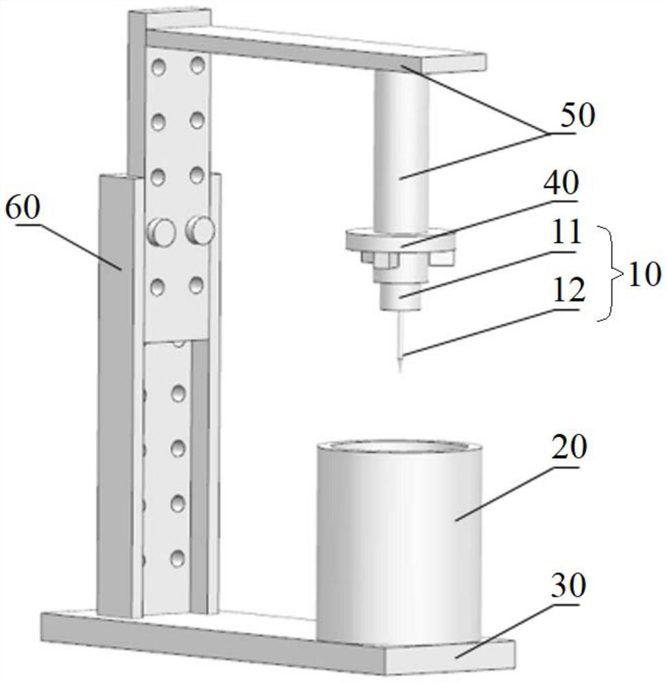
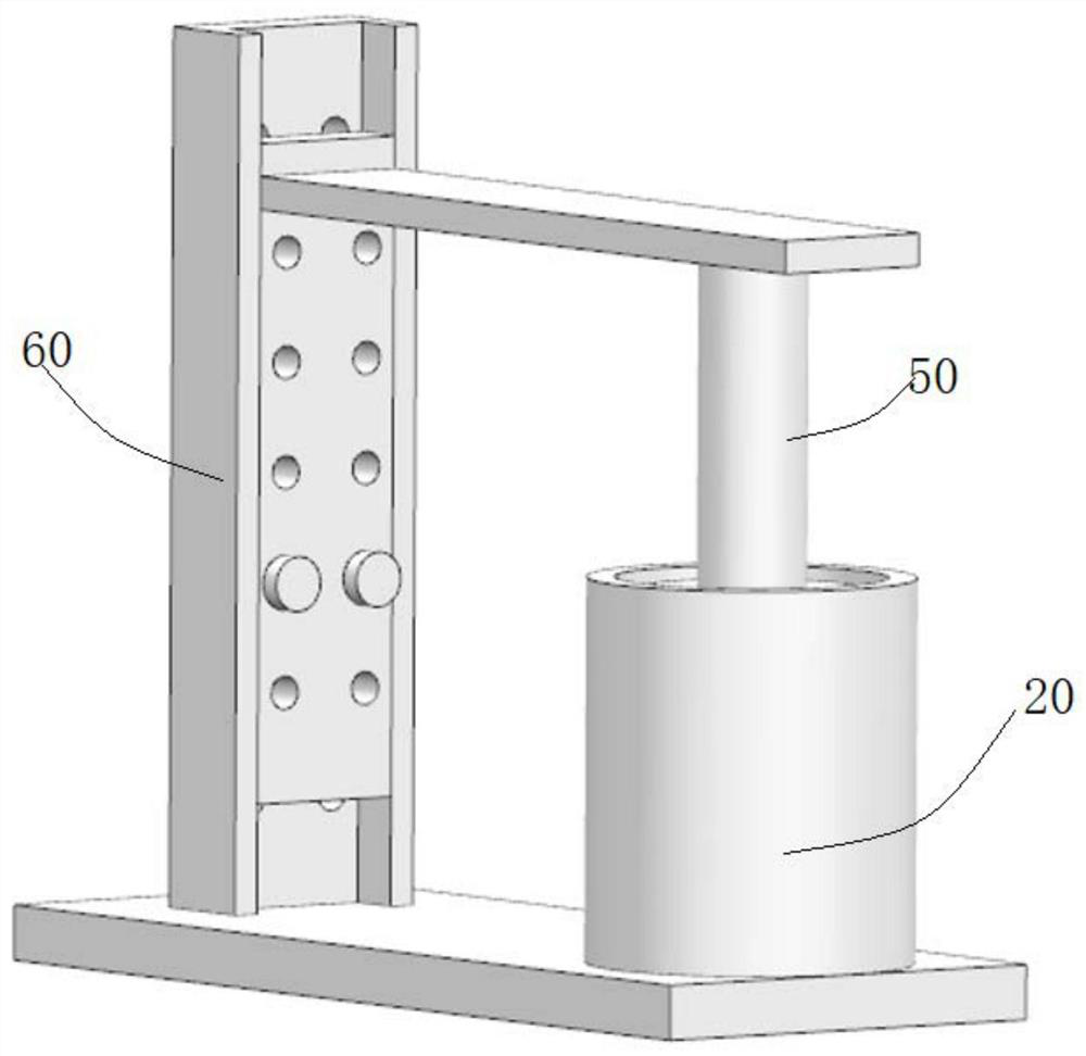
[0042]This embodiment provides a porous emission needle infiltration device, such as Figure 1~2 As shown, the porous emitting needle infiltration device includes an infiltration module 10 and a heating device 20 arranged vertically opposite to each other, wherein: the infiltration module 10 is configured to be able to move up and down relative to the heating device 20 to be in the first infiltration state, the second wetting state, or the third wetting state; the wetting module 10 includes a storage chamber 11 and a porous emission needle 12 that are coaxial and sequentially connected from top to bottom, and a solid state that is accommodated in the storage chamber 11 propellant; the first wetted state is as figure 1 As shown, it includes: the wetting module 10 is completely suspended above the heating device 20, and the pores of the porous emitting needles 12 are penetrated; the second wetting state is as follows figure 2 As shown, it includes: the infiltration module 10 i...

Embodiment 2

[0048] This embodiment provides an infiltration method for porous emission needles, the method includes: arranging the infiltration module 10 and the heating device 20 vertically opposite each other; the infiltration module 10 moves up and down relative to the heating device 20, To be in the first wetting state, the second wetting state or the third wetting state; the storage chamber 11 and the porous emission needle 12 of the wetting module 10 are connected coaxially and sequentially from top to bottom, and the solid propellant is placed in In the storage chamber 11; the first wetting state includes: the wetting module 10 is completely suspended above the heating device 20, and the pores of the porous emitting needles 12 penetrate; the second wetting state includes: the The wetting module 10 is completely submerged in the heating device 20, the heating device 20 is turned on, the propellant melts and flows into the pores of the porous emission needle 12 through gravity and cap...


PUM


Abstract

The invention provides an infiltration device and method for porous emission needles. The infiltration device for porous emission needles includes an infiltration module and a heating device arranged vertically opposite each other, wherein: the infiltration module is configured to move up and down relative to the heating device, so as to be in the first The wetting state, the second wetting state or the third wetting state; the wetting module includes coaxial and sequentially connected storage chambers and porous emission needles from top to bottom, and a solid propellant contained in the storage chamber; the first wetting state includes : The infiltration module is completely suspended above the heating device, and the pores of the porous emission needle are penetrated; the second infiltration state includes: the infiltration module is completely immersed in the heating device, the heating device is turned on, and the propellant melts and flows into the porous hole through gravity and capillary action The pores of the emission needle; the third wetting state includes: the heating device is turned off, and the propellant in the pores of the porous emission needle returns to a solid state, so as to complete the wetting work of the porous emission needle before assembly.

Description

technical field [0001] The invention relates to the field of electric propulsion technology, in particular to a device and method for infiltrating a porous firing needle. Background technique [0002] The traditional needle-type field emission electric thruster is an electric thruster based on liquid metal ion source technology. The emission needle is usually solid tungsten. After the metal propellant is heated and melted, it moves along The emission needle flows to the needle tip, is ionized under the action of a strong electric field and accelerates the ejection to generate thrust. The porous needle-type field emission electric thruster is a new type of field emission electric thruster. The emission needle is a porous structure with a large number of micron-sized holes inside. After the metal propellant is heated and melted, the capillary in the micropores inside the emission needle Under the action, it flows to the needle tip, is ionized by a strong electric field and ac...

Claims


Application Information

Patent Timeline
Patent Type & Authority Patents(China)
IPC IPC(8): F03H1/00
CPCF03H1/0006F03H1/0087
Inventor 郭登帅张锐严玲玲余勇黄志伟李敏谢祥华康小明吴勤勤
Owner INNOVATION ACAD FOR MICROSATELLITES OF CAS
Why Eureka
Try Eureka