Direct-acting type pressure regulator for compensating for spring effect
A technology of compensating springs and pressure regulators, which is applied in the direction of valve operation/release devices, function valve types, and lift valves. The effect of voltage regulation accuracy and high voltage regulation accuracy
- Summary
- Abstract
- Description
- Claims
- Application Information
AI Technical Summary
Problems solved by technology
Method used
Image

Examples
Embodiment Construction
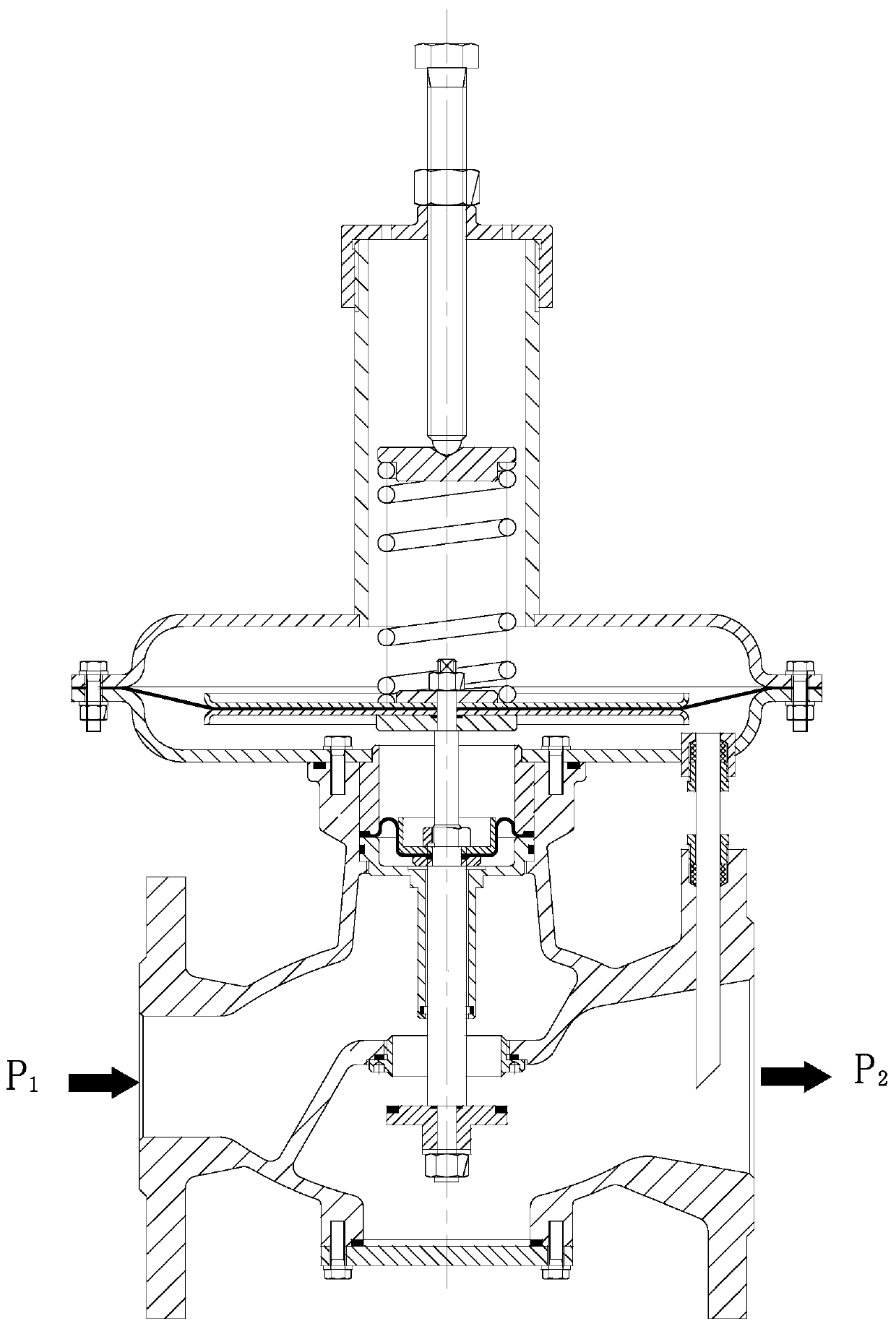
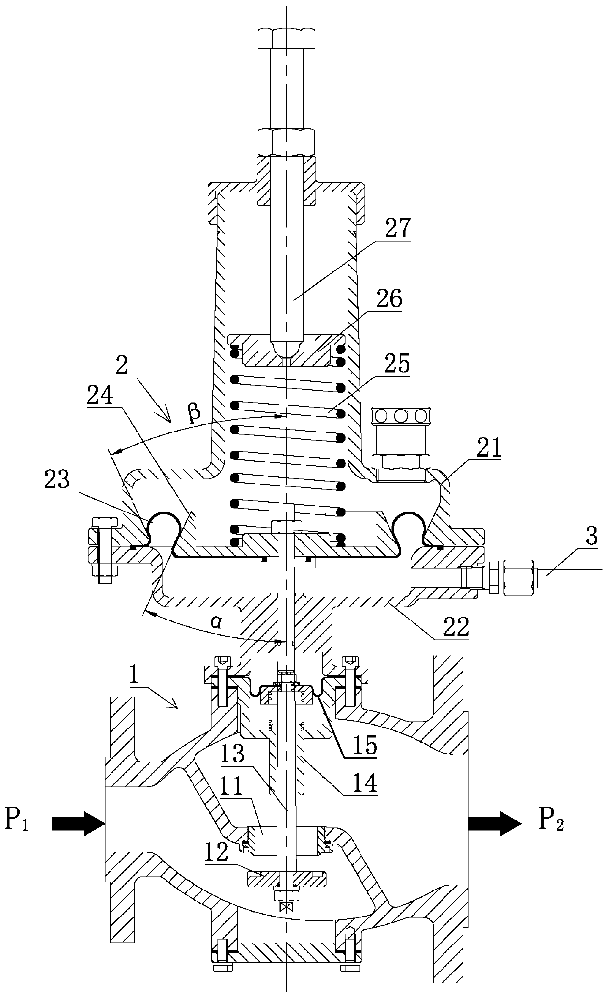
[0016] Such as figure 1 As shown, the structure of the pressure regulator in the prior art includes: the main valve body 1 and the driving assembly 2, the main valve body 1 is installed at the lower end of the driving assembly 2, and the main valve body 1 is equipped with a valve seat 11, a valve disc 12, a valve stem 13. Stem sleeve 14 and balance diaphragm 15, the valve stem sleeve 14 is fixed on the upper end of the main valve body 1, the valve stem 13 is set in the valve stem sleeve 14, the valve disc 12 is fixed on the lower end of the valve stem 13, and the valve disc 12 is located at the valve stem sleeve 14. On the lower side of the seat 11, the balance diaphragm 15 is installed on the upper side of the valve stem sleeve 14. The balance diaphragm 15 is set to improve the unbalanced force of the valve core, so that the outlet pressure can not be affected by the change of the inlet pressure to a certain extent. Improve voltage regulation accuracy. The drive assembly 2 i...
PUM
 Abstract
Description
Claims
Application Information
 - Generate Ideas
- Intellectual Property
- Life Sciences
- Materials
- Tech Scout
- Unparalleled Data Quality
- Higher Quality Content
- 60% Fewer Hallucinations
Browse by: Latest US Patents, China's latest patents, Technical Efficacy Thesaurus, Application Domain, Technology Topic, Popular Technical Reports.
© 2025 PatSnap. All rights reserved.Legal|Privacy policy|Modern Slavery Act Transparency Statement|Sitemap|About US| Contact US: help@patsnap.com