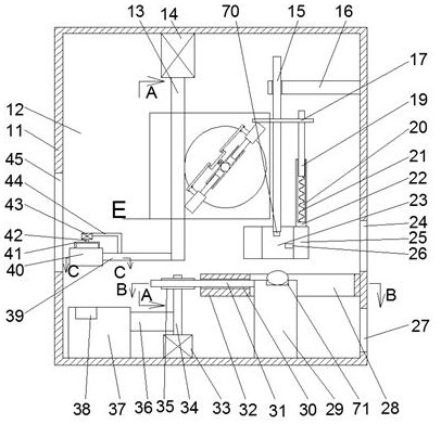
[0003] In order to solve the above problems, a metal characteristic analysis device is designed in this example. A metal characteristic analysis device in this example includes a frame, a cavity is provided in the frame, and a rotating shaft is provided for rotation in the cavity. , the lower end of the rotating shaft is fixedly connected with a connecting rod, that is, when the rotating shaft rotates, the connecting rod rotates around the rotating shaft, and the end of the connecting rod far away from the rotating shaft is fixedly connected with a cylindrical block, so A rotation block is arranged inside the cylindrical block, that is, the rotation block rotates in the cylindrical block, and a centrifugal chamber that penetrates up and down is provided in the rotation block, and two shafts about the A convex block symmetrical to the rotation center of the rotation block, each of which is provided with an opening facing the center of the rotation block, and a centrifugal block is slid in the opening, and the centrifugal block is provided with an opening facing the center of the rotation block. The moving cavity of the opening cavity, a clamping spring is connected between the end surface of the moving cavity close to the center of the rotation block and the end surface of the opening cavity away from the center of the rotation block, and the centrifugal block is close to the rotation block An upper clamping block and a lower clamping block are fixedly connected on the end surface of the center of the circle, the upper clamping block is located on the upper side of the lower clamping block, and the
surface friction coefficient of the upper clamping block is lower than that of the lower clamping block. The
friction coefficient on the surface of the block is small. An upper pressure gauge is fixedly connected to the end surface of the upper clamping block close to the center of the rotation block. The upper pressure gauge records the pressure received on the surface of the upper clamping block. A lower pressure gauge is fixedly connected to the end surface of the clamping block close to the center of the rotation block, and the lower pressure gauge records the pressure on the surface of the lower clamping block. In the initial state, the two upper clamping blocks and the two The surfaces of the two lower clamping blocks are in contact under the elastic force of the clamping spring, and the metal block to be measured is manually placed between the two upper clamping blocks to compress the clamping spring. , while the centrifugal block slides along the inner wall of the opening, and at the same time, the upper pressure gauge records the pressure received by the surface of the upper clamping block, and finally the pressure is multiplied by the
friction coefficient of the upper clamping block surface The weight of the metal block; if the friction coefficient on the surface of the upper pressure gauge is too small to clamp the metal block, the metal block will fall under the action of gravity to between the two lower clamping blocks with large
surface friction coefficients and is clamped by the lower clamping block, while the lower pressure gauge records the pressure on the surface of the lower clamping block, and finally the pressure is multiplied by the friction coefficient of the lower clamping block surface to obtain the metal block weight;

