
Computer network interconnector

A computer network and network interconnection technology, which is applied in the field of network equipment, can solve the problems of easy dust and dust in the wiring port, damage to the internal components of the outer casing, affecting the use of the network interconnector, etc. Easy to pick and place, not easy to come off by itself

Inactive Publication Date: 2020-08-25
刘毅新
View PDF9 Cites 0 Cited by
  • Summary
  • Abstract
  • Description
  • Claims
  • Application Information

AI Technical Summary

Problems solved by technology

[0003] The network interconnection of computers is usually completed through computer network interconnectors. The existing computer network interconnectors have the following problems in the use process: the network interconnector lacks a good protective structure outside the network interconnector, and the network interconnector is in the process of handling and taking. Among them, the network interconnector is easy to fall, causing damage to the external shell and internal components, which affects the use of the network interconnector; when the network interconnector is in a non-wiring state, the wiring port of the network interconnector is easy to get dust and dust. Poor contact of conductive components at wiring ports affects the use of network interconnectors; network interconnectors are mostly installed independently, usually fixed on the outer wall of the indoor wall, and the installation and removal of network interconnectors relative to the wall is inconvenient, affecting the use of network interconnectors Maintenance and replacement in the future, therefore, a computer network interconnector is needed to solve the above problems

Method used


Image

  • Computer network interconnector
  • Computer network interconnector
  • Computer network interconnector

Examples


Embodiment

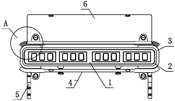
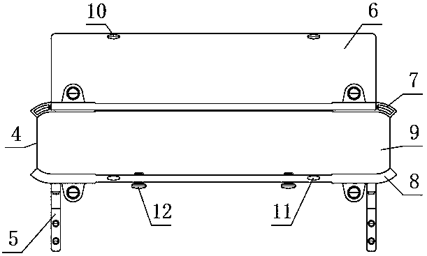
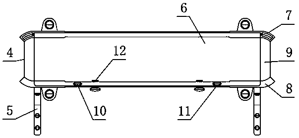
[0028] see Figure 1-8 , the present invention provides the following technical solutions: a computer network interconnector, including a network interconnector body 1 and a housing 4, a network interconnector body 1 is placed inside the housing 4, and the network interconnector body 1 is surrounded by a The sleeve frame 2 is connected together, and the outer surfaces of both sides of the sleeve frame 2 are fixed with pads 3, and the shell 4 includes an upper shell plate 7, a lower shell plate 8 and a back plate 9, and the upper shell plate 7 and the lower shell plate 8 pass through The back plate 9 is fixedly connected, one side surface of the upper shell plate 7 is connected with a transparent cover plate 6 through a rotating shaft, and the left and right ends of the bottom end surface of the lower shell plate 8 are fixedly connected with a triangular brace 5 through several fixing bolts. The left and right ends of the other side of the bottom end surface of the shell plate ...


PUM


Abstract

The invention belongs to the technical field of network equipment. The invention relates to a computer network interconnector. The network interconnector comprises a network interconnector body and ashell, wherein a network interconnector body is placed in the shell; the periphery of the exterior of the network interconnector body is connected with a sleeve frame in a sleeved mode; wrapping padsare fixed on the outer surfaces of the two sides of the sleeve frame; the shell comprises an upper shell plate, a lower shell plate and a back plate; the upper shell plate and the lower shell plate are fixedly connected through the back plate; the surface of one side of the upper shell plate is rotationally connected with a transparent cover plate through a rotating shaft; the left end and the right end of one side of the bottom end face of the lower shell plate are fixedly connected with triangular supports through a plurality of fixing bolts; limiting knobs are screwed at the left and rightends of the other side of the bottom end surface of the lower shell plate; and limiting rotary cylinders are fixed to the left end and the right end of one side of the bottom end face of the shell correspondingly. When the network interconnector is used, anti-falling protection of the side portion of the network interconnector body is facilitated through the sleeve frame and the wrapping pads, andmeanwhile the sleeve frame and the wrapping pads are convenient and rapid to assemble, disassemble and replace relative to the network interconnector body.

Description

technical field [0001] The invention belongs to the technical field of network equipment, and in particular relates to a computer network interconnector. Background technique [0002] Computer network interconnection refers to the connection of multiple local area networks (LAN) to form a large network. Each LAN becomes a component of this network. Such a network is called the Internet. In the Internet, the services and resources of a LAN It can be accessed by users on another LAN, and the communication in the Internet is transparent to users. Therefore, users regard the Internet as a large network system, and the purpose of network interconnection is to meet the growing needs of users. Realize high-speed, diversified and intelligent information, realize communication, distributed processing and resource sharing on a larger scale, and provide a powerful means and supporting environment for promoting the development of human civilization and prosperity. [0003] The network ...

Claims


Application Information

Patent Timeline
IPC IPC(8): H04Q1/02H04Q1/04
CPCH04Q1/02H04Q1/035H04Q1/04H04Q1/112
Inventor 刘毅新
Owner 刘毅新
Learn More