Large bus rearview mirror automatic cleaning device
An automatic cleaning and rearview mirror technology, applied in the direction of vehicle cleaning, vehicle maintenance, transportation and packaging, can solve problems such as difficulty in cleaning rearview mirrors, and achieve the effect of protecting cleanliness, improving safety, and reducing inconvenience
- Summary
- Abstract
- Description
- Claims
- Application Information
AI Technical Summary
Problems solved by technology
Method used
Image

Examples
Embodiment Construction
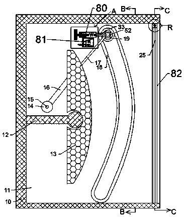
[0024] Combine below Figure 1-11 The present invention is described in detail, wherein, for the convenience of description, the orientations mentioned below are defined as follows: figure 1 The up, down, left, right, front and back directions of the projection relationship itself are the same.
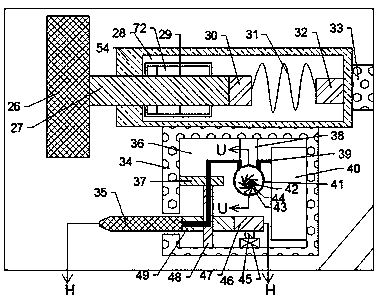
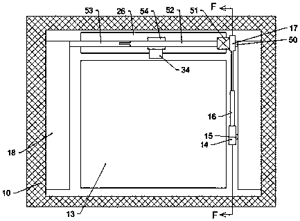
[0025] combined with Figure 1-11 The automatic cleaning device for a rearview mirror of a bus comprises a rearview mirror placement box 10, a rearview mirror placement chamber 11 is provided in the rearview mirror placement box 10, and the left side of the rearview mirror placement chamber 11 The inner wall is fixedly provided with a rearview mirror support 12, and the upper side of the rearview mirror support 12 is provided with a cleaning mechanism 80, and the cleaning mechanism 80 includes a telescopic cavity shell 54, and a telescopic cavity 28 is arranged in the telescopic cavity shell 54, so that A first slide rail 29 is fixed on the rear inner wall of the telescopic cavity 2...
PUM
 Abstract
Description
Claims
Application Information
PatSnap Eureka turns technology decisions into work you can execute. Powered by our Innovation Knowledge Graph, it runs expert workflows across engineering, life sciences, materials and intellectual property. Get your review-ready output in minutes.


