Sectioning equipment for plastic binding rope

A technology of bundling ropes and cutting sections, applied in the direction of metal processing, etc., can solve the problem of uneven cutting surface and achieve the effect of smooth cutting surface

Active Publication Date: 2020-08-28
浙江奕乌侬食品有限公司
View PDF6 Cites 6 Cited by
  • Summary
  • Abstract
  • Description
  • Claims
  • Application Information

AI Technical Summary

Problems solved by technology

[0005] In order to overcome the shortcomings in the prior art that people need to manually pull the plastic binding rope under the knife edge, and manual cutting will cause the cutting surface to be uneven, the pur

Method used


Image

  • Sectioning equipment for plastic binding rope
  • Sectioning equipment for plastic binding rope
  • Sectioning equipment for plastic binding rope

Examples


Example Embodiment

[0020] Example 1

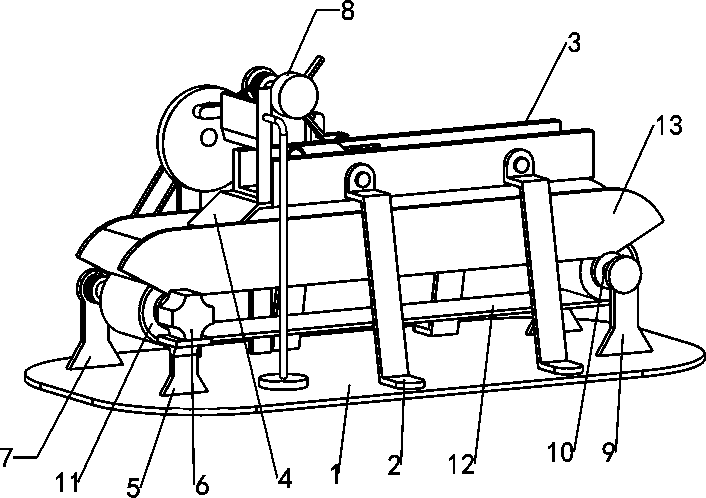
[0021] A cutting device for plastic strapping ropes, such as Figure 1-2 As shown, it includes a base 1, a support frame 2, a placement frame 3, a slant plate 4, a first bearing seat 5, a servo motor 6 and a cutting mechanism 7, and the support frame 2 is fixedly connected to the front and rear sides of the top of the base 1, and the support frame 2 The upper part is connected with a placement frame 3 by bolts, the left side of the placement frame 3 is fixedly connected with a slant plate 4, the top left front side of the base 1 is provided with a first bearing seat 5, the top of the first bearing seat 5 is installed with a servo motor 6, and the base 1 is provided with a cutting mechanism 7, and the output shaft of the servo motor 6 is connected with the cutting mechanism 7.

[0022] The cutting mechanism 7 includes a second bearing seat 70, a first rotating shaft 71, a third bearing seat 72, a second rotating shaft 73, a first pulley 74, a second pulley 7...

Example Embodiment

[0025] Example 2

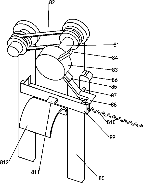
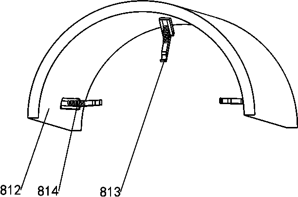
[0026] On the basis of Example 1, such as figure 1 and Figure 3-4As shown, it also includes a repeating displacement mechanism 8, the middle of the top of the base 1 is provided with a repeating displacement mechanism 8, and the repeating displacement mechanism 8 includes a fourth bearing seat 80, a third rotating shaft 81, a transmission assembly 82, a second turntable 83, a first Toggle lever 84, the second toggle lever 85, the fifth bearing seat 86, the fourth rotating shaft 87, special-shaped block 88, slide block 89, first spring 810, connecting block 811, arc plate 812, driving lever 813 and the first Two springs 814, a fourth bearing seat 80 is installed on the rear side of the top of the base 1, the fourth bearing seat 80 is located on the right side of the third bearing seat 72, and the fourth bearing seat 80 is internally rotated to be provided with a third rotating shaft 81, and the third rotating shaft 81 The rear part is provided with a trans...


PUM


Abstract

The invention relates to sectioning equipment, in particular to sectioning equipment for a plastic binding rope. The invention aims to provide the sectioning equipment for the plastic binding rope, which is capable of automatically transporting the plastic binding rope to a knife edge and has a flat cutting surface. The segmentation equipment for the plastic binding rope comprises a base, supporting frames and a placing frame; the base is in a long shape; the supporting frames are symmetrically and fixedly connected to the top of the base, and the number of the supporting frames is at least four; and the placing frame is connected between the upper parts of the supporting frames through bolts. According to the sectioning equipment for the plastic binding rope, the effects that the plasticbinding rope can be automatically conveyed to the knife edge, and the cutting face is smooth are achieved, and through clearance fit between a lifting lever and the plastic binding rope, the lifting rod can hook the plastic binding rope and drive the plastic binding rope to move leftwards together.

Description

technical field [0001] The invention relates to a segment cutting device, in particular to a segment cutting device for plastic binding ropes. Background technique [0002] In our daily life, we often need to use plastic binding ropes, which can be used to tie up things and avoid placing objects neatly. Plastic binding ropes are generally melted from plastic materials, then extruded or blown into films, and then cut into A narrow strip of a certain width is light in texture, durable, particularly strong in tensile strength, and has good ductility. [0003] When producing plastic binding ropes, the raw materials are usually put into the plastic binding rope equipment, and then the long strips of plastic binding ropes are produced through the equipment, and then cut into sections according to the requirements, and finally after traction, thermal stretching, winding And around the ball, when it is necessary to produce shorter plastic strapping ropes, workers usually manually p...

Claims


Application Information

Patent Timeline
IPC IPC(8): B26D1/08B26D5/08B26D5/14B26D7/06
CPCB26D1/08B26D5/08B26D5/086B26D5/14B26D7/06
Inventor 孙龙喜
Owner 浙江奕乌侬食品有限公司
Why Eureka
Try Eureka