Copper wire end identifier printing machine

A marking machine and marking technology, which is applied to printing machines, rotary printing machines, printing, etc., can solve the problems of manpower consumption and low work efficiency, and achieve the effects of improving work efficiency, simple operation, and saving manpower

Active Publication Date: 2020-08-28
江西源广顺科技协同创新有限公司 +1
View PDF5 Cites 2 Cited by
  • Summary
  • Abstract
  • Description
  • Claims
  • Application Information

AI Technical Summary

Problems solved by technology

[0003] At present, the copper wire is printed on the end of the copper wire by using a printing plate and a scraper to print manually. When the above method is operated, it is necessary to manually hold the printing plate and the scraper for printing. The operation is more labor-intensive and the printing Only one terminal can be printed at a time, and the work efficiency is low

Method used


Image

  • Copper wire end identifier printing machine
  • Copper wire end identifier printing machine
  • Copper wire end identifier printing machine

Examples


Embodiment 1

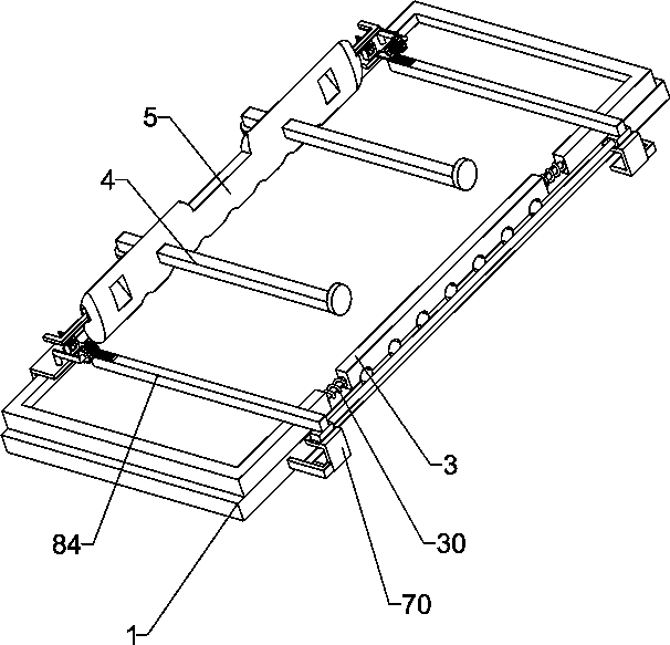
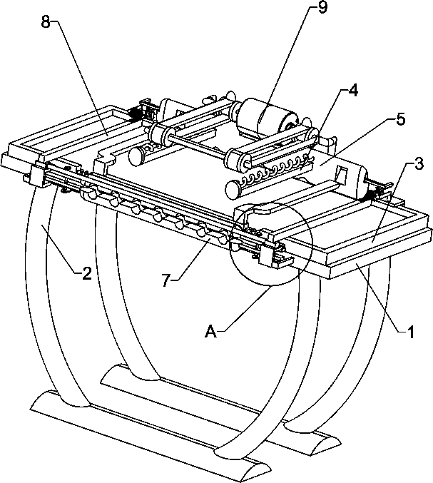
[0026] A copper wire terminal identification marking machine, such as Figure 1-5 As shown, it includes mounting plate 1, leg 2, printing frame 3, compression spring 30, L-shaped sliding rod 4, scraper 5 and telescopic spring 6, the bottom of mounting plate 1 is connected with leg 2, and the top of mounting plate 1 is connected There is a printing frame 3, the two sides of the printing frame 3 are sliding settings, a compression spring 30 is connected between the two sides and the middle of the printing frame 3, and the left and right sides of the rear part of the mounting plate 1 are slidably connected with L-shaped slide bars 4, and the two sides Scraper 5 is slidably connected between L-shaped sliding rods 4, telescopic spring 6 is connected between L-shaped sliding rods 4 and mounting plate 1, and also includes fixing device 7 and transmission device 8, mounting plate 1 and printing frame 3 A fixing device 7 is arranged between them, and a transmission device 8 is arranged...

Embodiment 2

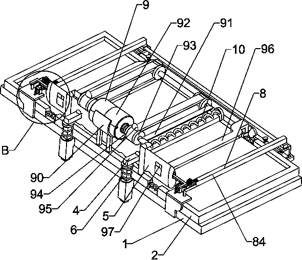
[0031] On the basis of Example 1, such as Figure 4As shown, drive device 9 is also included, and drive device 9 includes arc-shaped connecting plate 90, connecting frame 91, motor 92, sprocket wheel 93, chain 94, push plate 95 and guide rod 96, and the middle part of the rear side of printing frame 3 is connected There is an arc-shaped connecting plate 90, a connecting frame 91 is connected to the rear side of the printing frame 3, and a motor 92 is installed on the arc-shaped connecting plate 90. Wheel 93, chain 94 is wound around between two sprocket wheels 93, two sprocket wheels 93 points front and rear sides are arranged, and two sprocket wheels 93 of rear side are connected with two output shafts of motor 92 respectively, and chain 94 is connected with Push plate 95, printing frame 3 top left and right sides are all connected with guide rod 96, scraper 5 left and right sides all have guide hole 97, and guide hole 97 cooperates with guide rod 96.

[0032] When it is nec...


PUM


Abstract

The present invention relates to an identifier printing machine, particularly to a copper wire end identifier printing machine. The technical problem to be solved by the present invention is how to design a copper wire end identifier printing machine that can save the manpower and can once print multiple ends to improve the working efficiency. In order to solve the technical problem, provided in the present invention is such a copper wire end identifier printing machine, comprising: a mounting plate connected with support legs at the bottom; a printing frame connected to the top of the mounting plate, both sides of the printing frame being slidably arranged, and a compression spring being connected between both sides of the printing frame and the middle portion; and L-shaped slide rods, two of which are provided and slidably connected to both sides of the mounting plate respectively. The ends of copper wires are printed by means of cooperative operation of a scraper and the printing frame, so that the printing effect on the ends of the copper wires is achieved.

Description

technical field [0001] The invention relates to a label printing machine, in particular to a copper wire terminal identification label printing machine. Background technique [0002] Copper wire refers to the wire drawn from hot-rolled copper rods without annealing (but smaller wires may require intermediate annealing), which can be used for weaving nets, cables, copper brush filters, etc. Copper wire can be divided into brass, red copper and phosphor copper, etc. Copper wire is widely used in industrial filtration, petroleum, chemical, printing, art and other industries. Some copper wires will be printed on their ends after production, so as to achieve the effect of promoting the company's products. [0003] At present, the copper wire is printed on the end of the copper wire by using a printing plate and a scraper to print manually. When the above method is operated, it is necessary to manually hold the printing plate and the scraper for printing. The operation is more la...

Claims


Application Information

Patent Timeline
Patent Type & Authority Applications(China)
IPC IPC(8): B41F17/08
CPCB41F17/08
Inventor 孙晓风卢欣荣黄学雨谢小云
Owner 江西源广顺科技协同创新有限公司
Why Eureka
Try Eureka