Locking mechanism for locking steel rail

A locking mechanism and rail technology, applied in the direction of freight cars, cargo support/secure parts, railway car body parts, etc., can solve problems such as low locking efficiency

Active Publication Date: 2020-08-28
CRRC QIQIHAR ROLLING CO LTD
View PDF9 Cites 0 Cited by
  • Summary
  • Abstract
  • Description
  • Claims
  • Application Information

AI Technical Summary

Problems solved by technology

Each rail needs to perform such locking operat

Method used


Image

  • Locking mechanism for locking steel rail
  • Locking mechanism for locking steel rail
  • Locking mechanism for locking steel rail

Examples


Embodiment Construction

[0071] In order to enable those skilled in the art to better understand the technical solutions of the present invention, the present invention will be further described in detail below in conjunction with the accompanying drawings and specific embodiments.

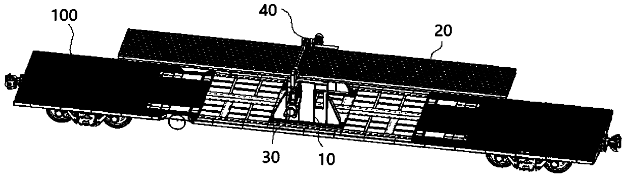
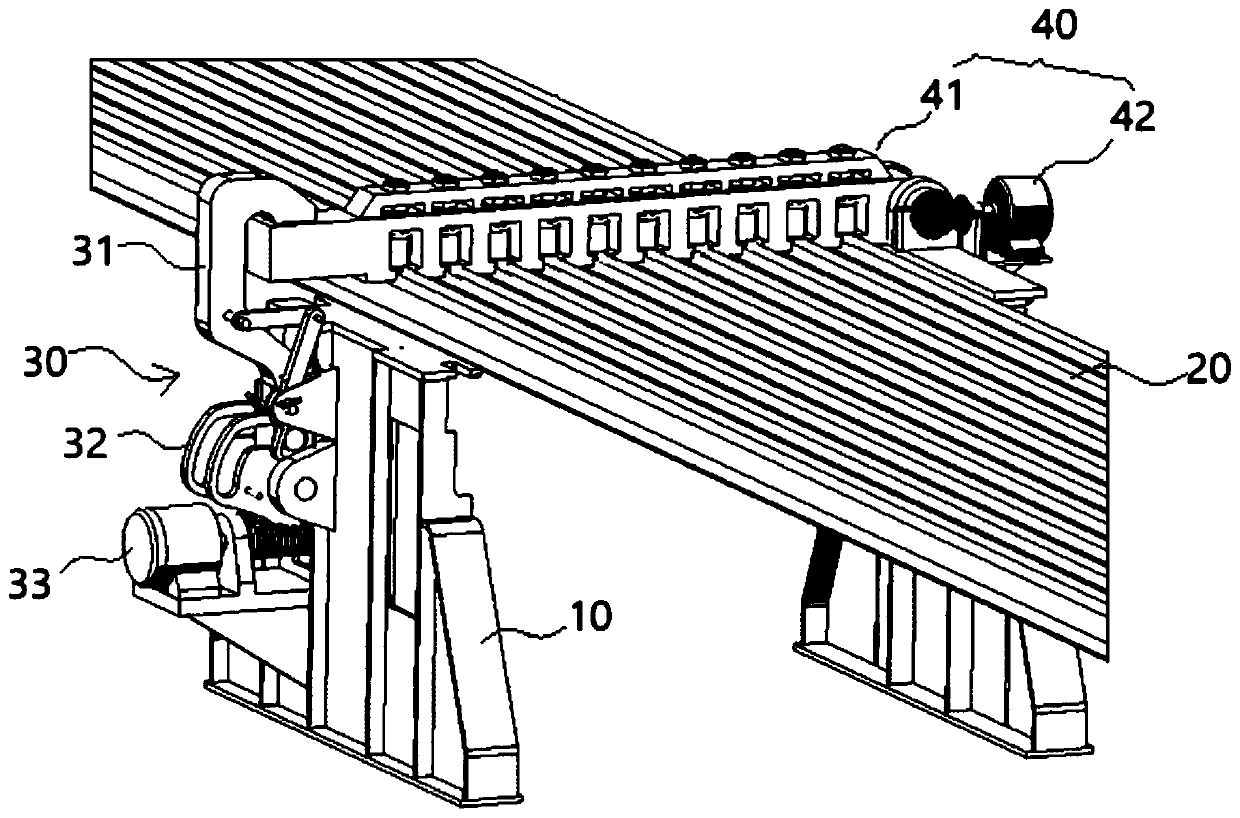
[0072] Please refer to figure 1 , 2 , figure 1 It is a structural schematic diagram of locking the rail on the rail train by the locking mechanism provided by the present invention; figure 2 A zoomed-in view of the position of the locking mechanism locking the abutment beam.

[0073] Such as figure 1 As shown, the locking mechanism includes bases 10 located on both sides of the pallet 100 of the rail train, and the bases 10 are supported and fixed on the pallet 100 . The locking mechanism also includes a pressing device 40 and a supporting base 20. The two sides of the supporting base 20 are respectively supported on the base 10 on both sides. The base 10 can be supported and fixed on the supporting plate 100, which ...


PUM


Abstract

The invention discloses a locking mechanism for locking a steel rail. The locking mechanism comprises an abutting device, a locking device and a supporting base used for supporting the multiple steelrails. The abutting device comprises an abutting beam and an abutting driving piece, and the abutting driving piece drives the abutting beam to rotate around one end so that to rotarily clamp and press to lock or rotarily open to unlock the multiple steel rails. When the abutting beam clamps and presses the multiple steel rails, the locking device is used for locking the other end of the abuttingbeam. According to the scheme, one abutting beam stretches across the multiple steel rails and abuts against the multiple steel rails from the upper portions of the steel rails at the same time, so that the multiple steel rails are locked at the same time, the steel rails are prevented from moving in the longitudinal direction, vertical moving of the steel rails is limited, and the steel rail locking efficiency can be greatly improved. Besides, the locking device is arranged to lock the free end of the abutting beam, the abutting locking reliability of the abutting beam can be guaranteed, andthe load requirement for the abutting driving piece is reduced.

Description

technical field [0001] The invention relates to the technical field of rail transportation, in particular to a locking mechanism for locking rails. Background technique [0002] Rail trains are railway engineering vehicles used for loading, transporting, and unloading long rails. The rail train has a pallet on which the rails to be transported are generally arranged in a layer on the pallet, the number of which can reach dozens, and the length of a rail is usually 400m. [0003] In order to prevent the rail from moving longitudinally on the pallet, a locking device is generally provided. The current locking device mainly includes locking weights, locking blocks and locking bolts. There are a set of locking weights and locking blocks on both sides of the bottom of the rail. Between them, tighten the locking bolt manually to lock the locking weight iron and the locking weight block to lock the rail. Each steel rail will carry out such locking operation successively, and lock...

Claims


Application Information

Patent Timeline
IPC IPC(8): B61D45/00B61D3/16
CPCB61D3/16B61D45/001
Inventor 李志刚杨富伊永峰白雪李晓伟
Owner CRRC QIQIHAR ROLLING CO LTD
Why Eureka
Try Eureka