Coupling device for elimination of backlash

A technology of coupling device and side clearance, applied in the direction of coupling, elastic coupling, mechanical equipment, etc., can solve the problems of small size and complicated manufacturing, and achieve the effect of easy production and installation, low cost and high practicability

Inactive Publication Date: 2017-05-31
BEIJING INST OF RADIO MEASUREMENT
View PDF3 Cites 0 Cited by
  • Summary
  • Abstract
  • Description
  • Claims
  • Application Information

AI Technical Summary

Problems solved by technology

A machine with a large diameter (600mm in diameter) and a shaft angle measuring device integrated on the device requires a coupling device to accurately transmit the motion position. However, the traditional coupling device that accurately transmits the motion position is small in size And the manufacturing is complicated and cannot meet the current demand

Method used


Image

  • Coupling device for elimination of backlash
  • Coupling device for elimination of backlash
  • Coupling device for elimination of backlash

Examples


Embodiment Construction

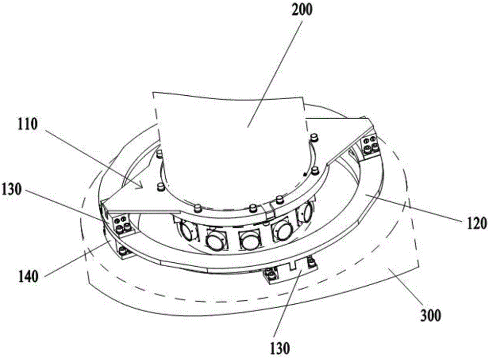
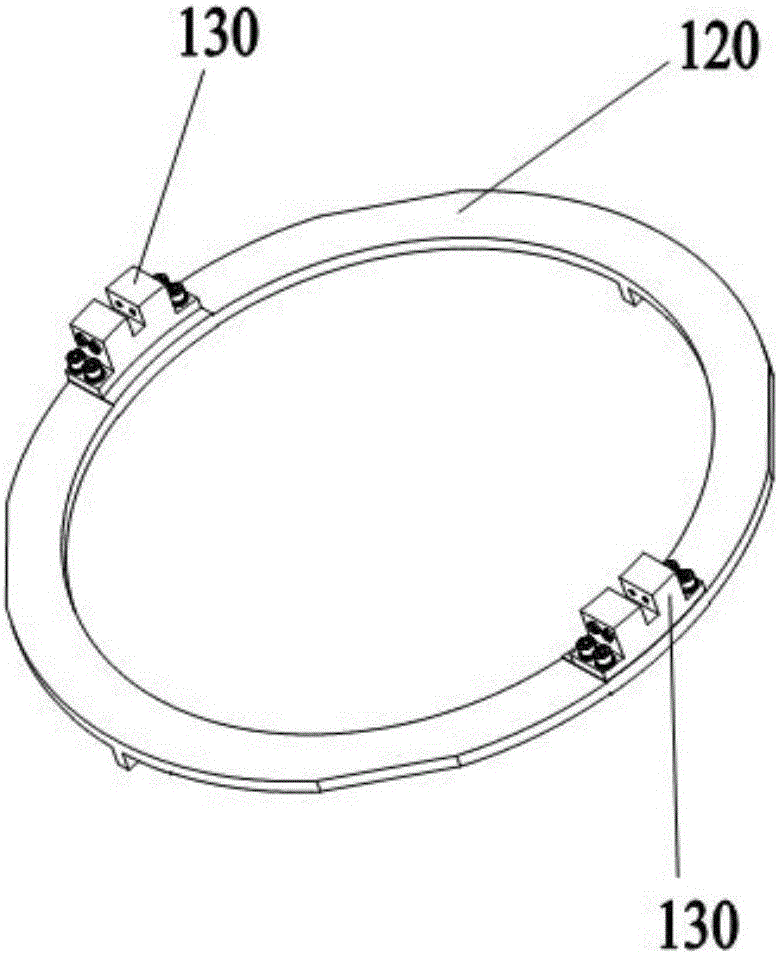
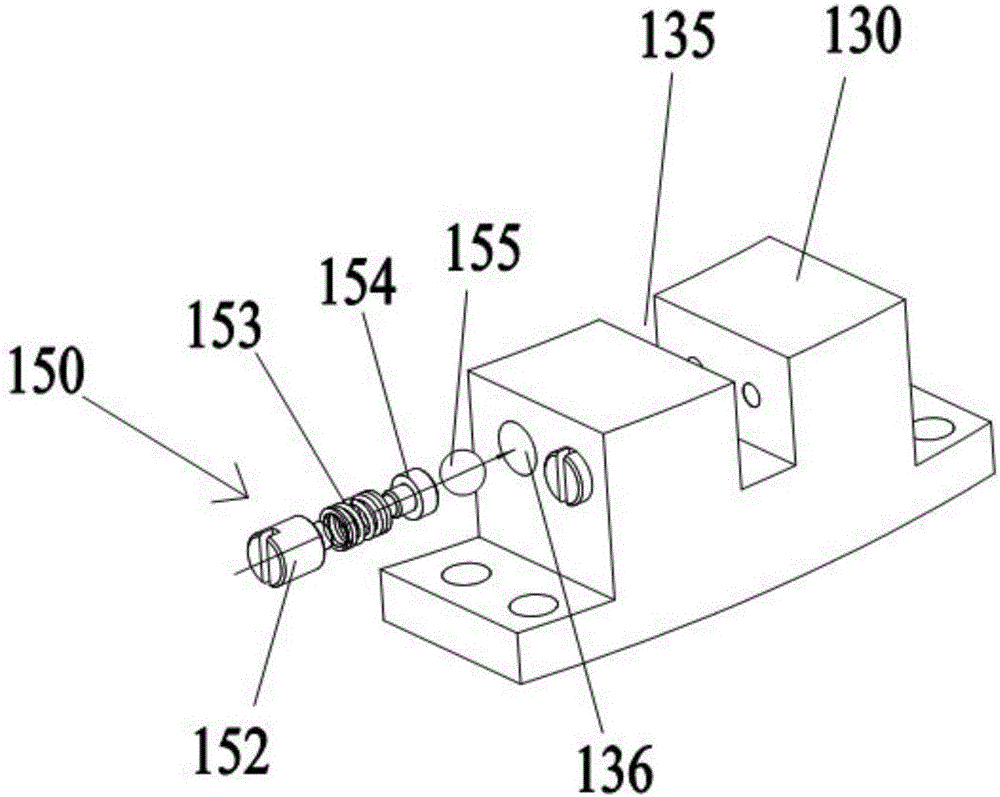
[0028] like Figure 1 to Figure 6 As shown, the coupling device for eliminating backlash provided by the present invention includes a dial 110 and a sliding plate 120, the dial 110 is installed on the output shaft 200, and the lower surface of the dial 110 is provided with several dial flanges 1156 , the upper surface of the sliding plate 120 is equipped with a number of sliding seats 130 corresponding to the dial flanges 1156 one by one, the upper surface of the sliding seat 130 is provided with grooves 135, and the dial flanges 1156 are snapped into the grooves of the corresponding sliding seats 130 within 135;

[0029] The lower surface of the sliding plate 120 is evenly provided with several sliding plate flanges 125, and the input shaft 300 is equipped with a number of sliding seats 130 corresponding to the sliding plate flanges 125 one by one, and the sliding plate flanges 125 are clamped on the corresponding sliding seats 130. In the groove 135.

[0030] As a possible...


PUM


Abstract

The invention discloses a coupling device for elimination of backlash, which comprises a driver plate and a sliding plate. The driver plate is mounted on an output shaft. A plurality of driver plate flanges are arranged on the lower surface of the driver plate, and a plurality of sliding seats corresponding to the driver plate flanges one to one are mounted on the upper surface of the sliding plate. Grooves are provided in the upper surface of the sliding seats and the driver plate flanges are clamped in the grooves of the corresponding sliding seats. A plurality of sliding plate flanges are uniformly arranged on the lower surface of the sliding plate, and a plurality of sliding seats corresponding to the sliding plate flanges one to one are mounted on an input shaft. The sliding plate flanges are clamped in grooves of the corresponding sliding seats. The coupling device for elimination of backlash is simple in structure, convenient to use, convenient to fabricate and mount, low in cost, and small in mounting error with tremendous practicability.

Description

technical field [0001] The invention relates to a shaft coupling device, in particular to a shaft coupling device for eliminating backlash. Background technique [0002] Couplings are mainly used to connect shafts to shafts to transmit motion and torque. Couplings are tolerant of axial, radial and tilt errors between the coupled shafts due to fabrication and installation. A machine with a large diameter (600mm in diameter) and a shaft angle measuring device integrated on the device requires a coupling device to accurately transmit the motion position. However, the traditional coupling device that accurately transmits the motion position is small in size And the manufacturing complexity cannot meet the current demand. Contents of the invention [0003] Aiming at the above technical problems, the present invention provides a coupling device for eliminating backlash which is simple in structure, easy to use, easy to manufacture and install, low in cost and small in installa...

Claims


Application Information

Patent Timeline
Patent Type & Authority Applications(China)
IPC IPC(8): F16D3/04
CPCF16D3/04
Inventor 王笃星魏秋云
Owner BEIJING INST OF RADIO MEASUREMENT
Why Eureka
Try Eureka