Eureka AIR delivers breakthrough ideas for toughest innovation challenges, trusted by R&D personnel around the world.

Safety protection device for hoisting machine

A technology of safety protection device and hoisting machinery, which is applied in mechanical equipment, transportation and packaging, load hanging components, etc. Small risk, the effect of protecting safety

Active Publication Date: 2020-08-28
蚌埠高灵传感系统工程有限公司
View PDF6 Cites 1 Cited by
  • Summary
  • Abstract
  • Description
  • Claims
  • Application Information

AI Technical Summary

Problems solved by technology

[0002] Hoisting machinery refers to electromechanical equipment used for vertical lifting or vertical lifting and horizontal moving of heavy objects. Its scope is defined as lifts with a rated lifting capacity greater than or equal to 0.5t; Cranes equal to 2m and electric hoists with fixed load-bearing forms, etc. Lifting operation is an industrial process of transporting mechanical equipment or other objects from one place to another. The working process generally includes lifting, running, falling and returning to the original place. Positioning and other steps, and when moving larger objects, certain dangers may occur. 1. Since the current hoisting machinery cannot fix the objects when retrieving materials, there are certain risks in the lifting process of the objects. 2. 1. There is no certain buffer when retrieving materials, which leads to unstable lifting of the machine and is prone to danger. 3. The existing device is easy to cause objects to collide, resulting in damage to the objects. Therefore, we propose a lifting machinery safety protection device

Method used


Image

  • Safety protection device for hoisting machine
  • Safety protection device for hoisting machine
  • Safety protection device for hoisting machine

Examples


Embodiment Construction

[0025] In order to make the technical means, creative features, goals and effects achieved by the present invention easy to understand, the present invention will be further described below in conjunction with specific embodiments.

[0026] In the description of the present invention, it should be noted that the terms "upper", "lower", "inner", "outer", "front end", "rear end", "both ends", "one end", "another end" The orientation or positional relationship indicated by etc. is based on the orientation or positional relationship shown in the drawings, and is only for the convenience of describing the present invention and simplifying the description, rather than indicating or implying that the referred device or element must have a specific orientation, use a specific Azimuth configuration and operation, therefore, should not be construed as limiting the invention. In addition, the terms "first" and "second" are used for descriptive purposes only, and should not be understood ...


PUM


Abstract

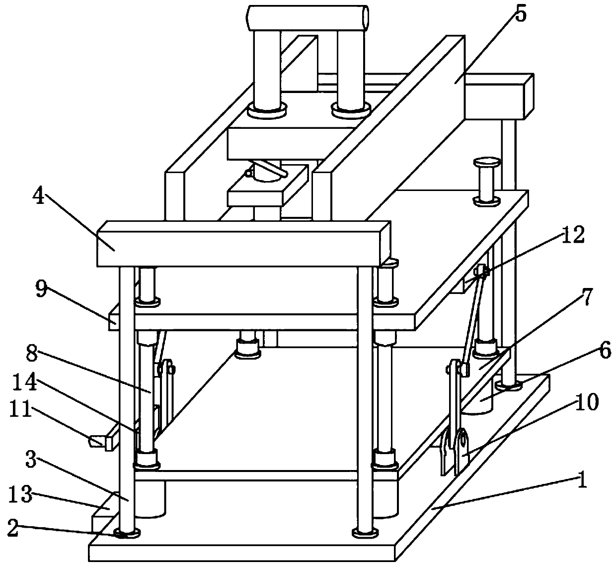
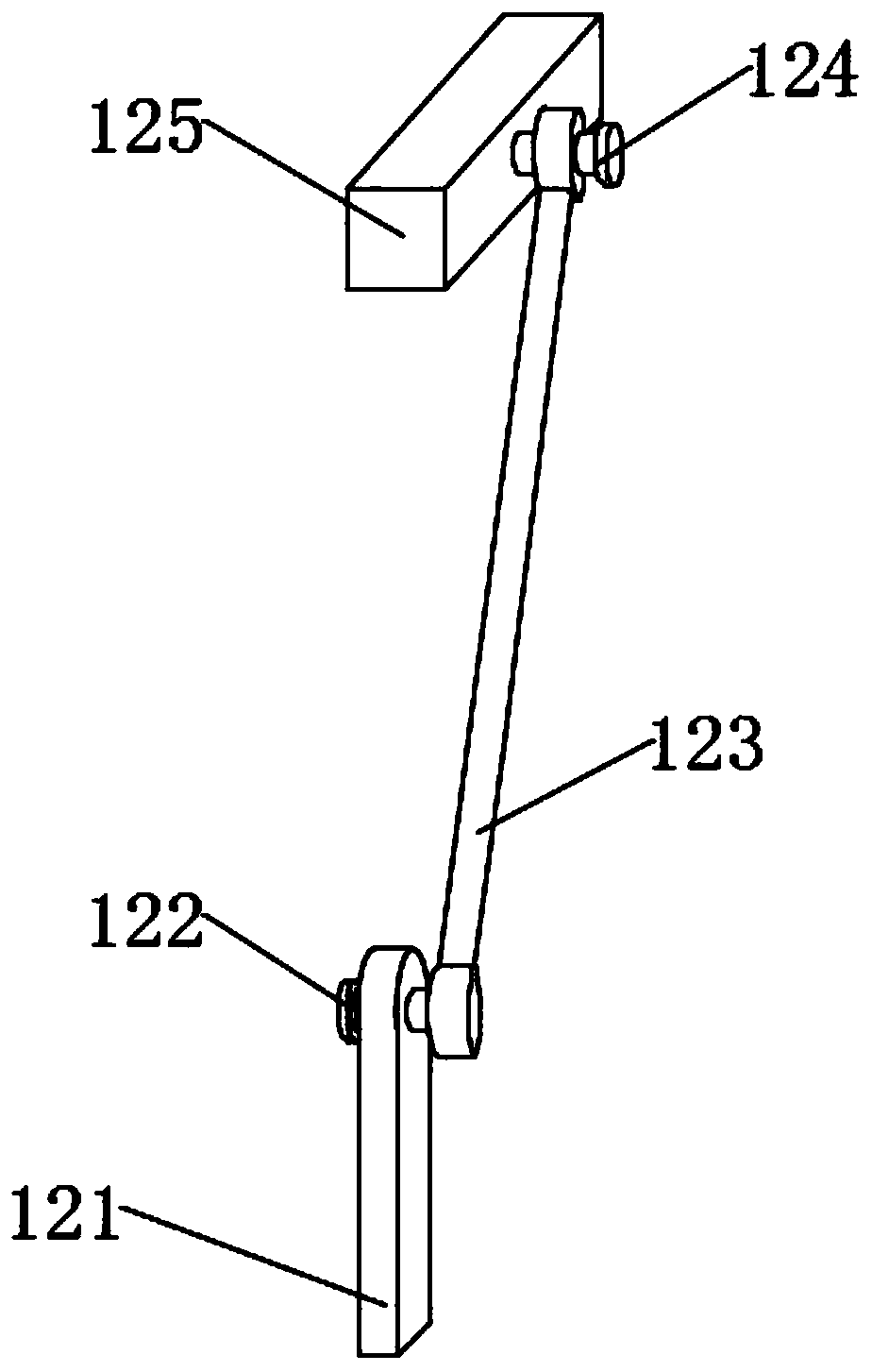
The invention discloses a safety protection device for a hoisting machine. The device comprises a base, four bottom plates are fixedly connected to the upper end of the base at equal intervals, supporting columns are fixedly connected to the middles of the upper ends of the bottom plates, the upper ends of the two supporting columns at the front part and the upper ends of the two supporting columns at the rear part are both fixedly connected with transverse plates, and a lifting device is fixedly connected between the transverse plates. Four connecting columns are fixedly connected to the middle of the upper end of the base at equal intervals, the upper ends of the four connecting columns are fixedly connected with a pedestal, four sliding devices are fixedly connected to the upper end ofthe pedestal at equal intervals, and the left and right portions of the upper end of the base are both fixedly connected with two connecting bases. A transmission device is in movable insertion connection with the four connecting bases, the left and right portions of the transmission device are both in fixed insertion connection with a lifting device. According to the safety protection device forthe hoisting machine, the transmission device is arranged, so that the transmission device drives a pressing plate to fastening articles through the lifting devices.

Description

technical field [0001] The invention relates to the field of hoisting machinery safety, in particular to a hoisting machinery safety protection device. Background technique [0002] Hoisting machinery refers to electromechanical equipment used for vertical lifting or vertical lifting and horizontal moving of heavy objects. Its scope is defined as lifts with a rated lifting capacity greater than or equal to 0.5t; Cranes equal to 2m and electric hoists with fixed load-bearing forms, etc. Lifting operation is an industrial process of transporting mechanical equipment or other objects from one place to another. The working process generally includes lifting, running, falling and returning to the original place. Positioning and other steps, and when moving larger objects, certain dangers may occur. 1. Since the current hoisting machinery cannot fix the objects when retrieving materials, there are certain risks in the lifting process of the objects. 2. 1. There is no certain buff...

Claims


Application Information

Patent Timeline
Patent Type & Authority Applications(China)
IPC IPC(8): B66C1/10B66C13/06F16F15/04F16F15/067
CPCB66C1/10B66C13/06F16F15/04F16F15/067
Inventor 李峰左妮娜宋玮琦
Owner 蚌埠高灵传感系统工程有限公司
Why Eureka
Eureka Blog
Learn More